





Profile and LED strip matching tables: the complete guide for electricians
Matching an LED strip to an aluminum profile means choosing two things together: a PCB width compatible with the housing and a power per meter compatible with the profile's heat dissipation capacity. The tables in this guide associate each Ledpoint profile family with the maximum power that can be safely installed, avoiding overheating, lumen depreciation, and premature failures.
Those who install LED strips professionally know: the critical moment is not the installation, it's the selection. A wrong profile doesn't show up on the day of testing. It shows up six months later, when the client calls because "the light has turned yellow in one spot", or two years later, when a section goes completely dark and you have to return to the site to dismantle a ceiling that's already been plastered and painted. In the vast majority of cases, the cause is not the quality of the strip, but a thermal coupling error: a high-power strip inserted into a profile that doesn't have enough aluminum surface area to dissipate the heat.
This guide was created to solve that problem at its root. It's not a general article: it's a job site tool. You'll find profile-by-profile matching tables, correction coefficients for diffuser, recessed mounting, IP rating and ambient temperature, voltage drop tables, lumens-per-application tables, and a section dedicated to neon flex and their mounting accessories. Everything refers to the actual catalog of Ledpoint aluminum profiles for LED strips and Ledpoint LED strips, with product codes that can be used when ordering.
In this article...
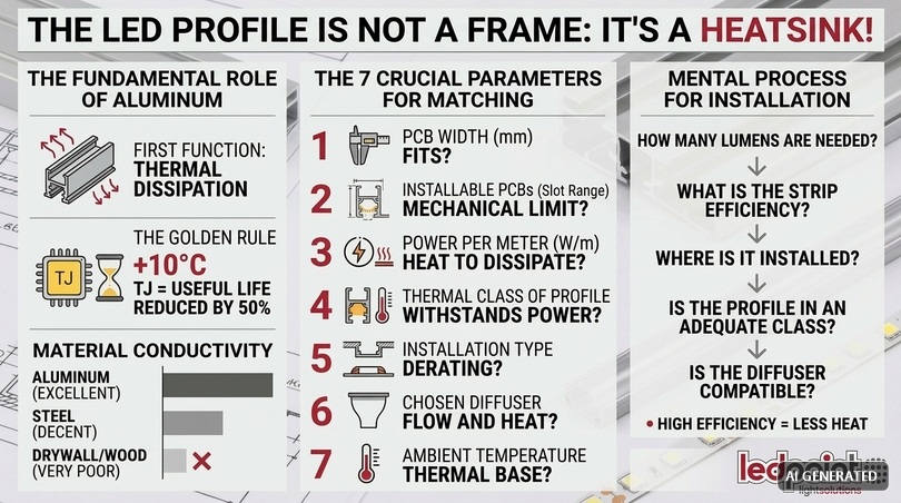
1. The profile is not a frame: it's a heat sink
The first mental shift to make, and for many installers it's counterintuitive, concerns the function of the aluminum profile. In the catalog you see it as an aesthetic element and mechanical protection: it hides the strip, evens out the light with the diffuser, protects the circuit from dust and impacts. All true. But from an electrical engineering perspective the profile is first and foremost a heat sink, and its sizing must be treated with the same seriousness with which you size a cable cross-section or the capacity of a circuit breaker.
An LED strip converts only a fraction of the energy it absorbs into light. The rest becomes heat, and that heat has to go somewhere. In a 14.4 W/m strip with 110 lm/W efficiency, about 60-65% of the absorbed power transforms into thermal energy that must be dissipated by the printed circuit board. The PCB of an LED strip is thin (typically 0.2÷0.4 mm of copper on FR4 or aluminum base) and has very limited vertical dissipation capacity. If you place it on a non-conductive surface (wood, drywall, PVC, or worse still if you leave it suspended in air inside a closed cove), the heat accumulates at the chip junction.
Why junction temperature determines product life
The parameter that matters is called Tj, junction temperature. It's the temperature of the semiconductor inside the LED chip, and it's not directly measurable on site: it's estimated from the solder point temperature (Ts) plus the thermal resistance of the package. Manufacturers qualify LEDs according to the LM-80 standard, which measures lumen depreciation at controlled Ts (typically 55 °C, 85 °C and 105 °C) for at least 6,000 hours, and then project useful life with the TM-21 method.
The result of those tests is always the same, for any serious manufacturer: LED life drops non-linearly as temperature increases. It's not a proportional deterioration, it's an exponential deterioration. The practical rule used in lighting design is that every 10 °C increase in Tj, above the component's comfort threshold, reduces useful life by roughly half.
The following table translates this concept into numbers you can use to explain to the client why the profile costs and why it's not an optional accessory.
| Solder point temperature (Ts) | Typical installation condition | Estimated L70 useful life (indicative) | Expected chromatic depreciation | Judgment |
|---|---|---|---|---|
| ≤ 45 °C | Generous profile, 20-25 °C environment, moderate power | > 50,000 h | Negligible | Optimal |
| 50-60 °C | Correctly sized profile with diffuser | 40,000-50,000 h | Very limited | Correct |
| 65-75 °C | Undersized profile or closed recess | 20,000-30,000 h | Perceptible after 2-3 years | Critical |
| 80-90 °C | High power strip without adequate profile | 8,000-15,000 h | Obvious yellowing | To be avoided |
| > 95 °C | Strip in closed cove, no dissipation | < 6,000 h | Rapid shift, spots | Almost certain failure |
The jump between the third and fourth row is what ruins jobs. A strip installed at 85 °C Ts works perfectly on the day of testing: it lights up, doesn't flicker, the client is happy. The problem manifests months later, when the installer has already been paid and the warranty becomes a topic of discussion.
What aluminum concretely does
Aluminum has a thermal conductivity of around 200-230 W/mK depending on the alloy (extrusions for lighting profiles are typically 6063 T5 alloy). Compare it with the materials installers typically mount strips on without a profile:
| Support material | Indicative thermal conductivity (W/mK) | Heat dissipation capacity | Recommended use with LED strips |
|---|---|---|---|
| Aluminum 6063 (profiles) | 200-230 | Excellent | Any power, within section limits |
| Steel | 45-55 | Fair | Acceptable only with low powers |
| Glass | 0.8-1.0 | Poor | Only strips ≤ 4.8 W/m |
| Drywall | 0.20-0.25 | Very poor | Never without profile |
| Wood / MDF | 0.12-0.18 | Very poor | Never without profile |
| PVC / polycarbonate | 0.17-0.22 | Very poor | Never without profile |
| Still air (closed cove) | 0.026 | Virtually none | Worst possible condition |
Look at the last row. Still air inside a closed drywall cove is the worst insulator you can put around an LED strip. It's exactly the situation that occurs when the designer draws a luminous cove without providing for the profile and the electrician simply glues the strip to the edge of the board. The strip finds itself surrounded by insulating material on three sides and stagnant air on the fourth.
Why aluminum cross-section matters more than width
A common mistake is to evaluate the profile by its external width: "it's 20 mm wide, it will definitely fit". The width serves to establish whether the strip fits, i.e. mechanical compatibility. The dissipation capacity depends instead on two different quantities: the mass of aluminum per linear meter (measured in grams per meter and directly correlated to the cross-sectional area of the solid) and the external surface area exposed to air (measured in cm² per linear meter).
A flat, wide profile with very thin walls can have less aluminum mass than a narrow but tall profile with thick walls, and dissipate worse while appearing "larger". This is why in the tables in chapters 5-12 you'll always find the two pieces of information side by side: the useful PCB width, which answers the question "does it fit?", and the thermal class, which answers the question "can it handle it?".
There's then a third factor, often ignored, which is how the profile is installed. The exact same profile, with the same strip, behaves differently if it's surface-mounted on a wall (air circulates freely on three sides), if it's recessed in a false ceiling (part of the surface is in contact with insulating material), if it's embedded in screed (conduction to the floor helps, but the heat has no air paths) or if it's inside a closed cabinet (the air inside progressively heats up and the reference temperature rises).
2. The seven parameters that determine the match
Before going to the tables, it's worth establishing the method. Every profile-strip match is resolved by checking seven parameters in sequence. If you skip even one step, the risk is discovering the problem on site with the material already delivered.
| # | Parameter | Where you read it | What question it answers | Typical error if you skip it |
|---|---|---|---|---|
| 1 | Strip PCB width | Strip technical datasheet (mm) | Does the strip fit in the housing? | 12 mm strip ordered for 8 mm profile |
| 2 | Installable PCBs in the profile | "Installable PCBs" field in profile datasheet | What is the mechanical limit? | Forcing the strip, adhesive detachment |
| 3 | Power per meter (W/m) | Strip technical datasheet | How much heat do I need to dissipate? | Overheating and premature depreciation |
| 4 | Profile thermal class | Tables in chapters 5-12 of this guide | Can the profile handle that power? | Failure within 12-24 months |
| 5 | Type of installation | Project / site survey | How much derating do I need to apply? | Theoretical calculation correct but inapplicable |
| 6 | Chosen diffuser | Profile options | How much flux do I lose and how much heat does it retain? | Final lux below expectations |
| 7 | Ambient temperature | Survey / intended use | What is the thermal starting base? | Underestimation in false ceilings and showcases |
Parameter number 2 deserves a note, because it's what makes everything else immediately operational. On Ledpoint profile product datasheets there's an explicit field called "Installable PCBs" that reports the maximum width of printed circuit board that can be housed in the seat. To give a concrete and verifiable example, the 17x8mm aluminum profile PR-SL08-03 declares installable PCBs up to 12 mm: this means it accepts without forcing any standard strip of 8, 10 or 12 mm width, while a 15 mm strip (typical of some RGBW and certain high-power COBs) must be excluded a priori.
This field is the contractual reference. The thermal classes you find in the tables of this guide are instead prudent sizing criteria built on the aluminum cross-section, the dissipating surface area and typical installation conditions: they serve to guide the selection and avoid blatantly wrong matches, and must always be cross-referenced with the datasheet data and the PDF datasheet downloadable from each profile's page.
The decision flow in five questions
If I had to reduce everything to a mental procedure to apply in thirty seconds in front of the client, it would be this:
| Step | Question | If the answer is A | If the answer is B |
|---|---|---|---|
| 1 | How many lumens per meter are needed? | Up to 1,200 lm/m → low power | Over 2,000 lm/m → high power |
| 2 | What efficiency does the chosen strip have? | > 140 lm/W → fewer watts for the same lumens | < 100 lm/W → more watts, more heat |
| 3 | Where will it be installed? | Surface mount → minimal derating | Recessed or enclosed → strong derating |
| 4 | Is the profile I chose in an adequate class? | Yes → verify the PCB and proceed | No → move up a class or reduce W/m |
| 5 | Is the diffuser compatible with the desired output? | Yes → close the bill of materials | No → review lumens and/or optics |
Note step 2 carefully, because it's the most underestimated and the most profitable. A high-efficiency strip solves thermal problems before they even arise: if you need 2,000 lumens per meter you can get them with 14.4 W/m using a 155 lm/W product, or you can use 20 W/m using a 100 lm/W product. In the first case the heat to dissipate is almost a third less and more compact, cheaper and easier-to-hide profiles open up to you.
3. PCB width: the first table to consult
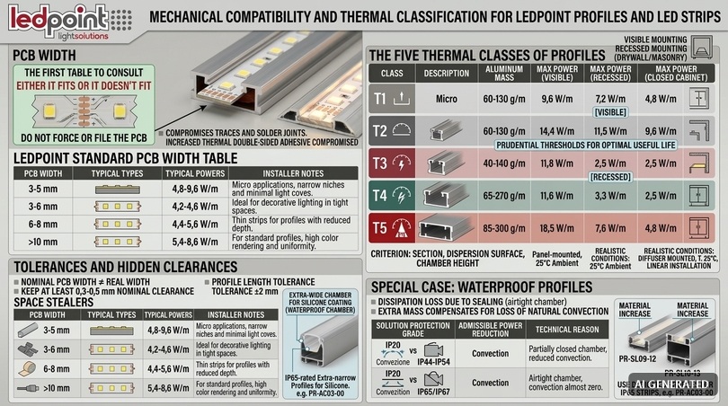
Mechanical compatibility is binary: either the strip fits, or it doesn't. There are no gray areas, and there are no acceptable creative solutions. Filing the PCB edges is a practice that compromises the copper traces and product compliance; forcing a wide strip into a narrow housing means deforming the circuit, stressing the LED solder joints and preventing uniform adhesion of the adhesive, which is precisely the element that guarantees thermal contact with the aluminum.
In the Ledpoint LED strips catalog the standard widths are few and recurring. Knowing them by heart avoids half of ordering errors.
| PCB Width | Typical types | Usual powers | Notes for the installer |
|---|---|---|---|
| 3-5 mm | Micro strips 2216, 2016, 0807, ultra-thin COBs | 4.8-9.6 W/m | For minimal coves, furniture, showcases and niches of a few millimeters |
| 6-8 mm | Low density 2835, compact COBs, some CCT | 4.8-14.4 W/m | The most common compromise in furniture and thin profiles |
| 10 mm | The market standard: 2835, COB, CCT, many RGB | 4.8-24 W/m | Compatible with almost all profiles in the catalog |
| 12 mm | RGB, RGBW, high density, high power | 14.4-30 W/m | Requires housing declared at least 12 mm |
| 14-15 mm | RGBW and RGBCCT four/five channel, double COBs | 19.2-36 W/m | Always verify: many compact profiles exclude it |
| 16-20 mm | 230V strips, high power professional, double row | 10-45 W/m | Only wide and tall profiles, often suspended |
| > 20 mm | Bars, modules and special solutions | Variable | Verify case by case the dedicated profile |
The tolerance to always keep in mind
A practical detail that makes a difference on site: the declared PCB width is nominal, and the profile housing has an extrusion tolerance. Always work with at least 0.3-0.5 mm of nominal clearance, and consider that the length of profiles and diffusers has a declared tolerance of about ±2 mm, a datum to keep in mind when designing continuous lines with flush joints.
Also pay attention to two elements that take up space and that don't appear in the PCB width on the datasheets:
| Element | Additional space required | When it matters | How to manage it |
|---|---|---|---|
| Silicone IP65 jacket | +1.5 / +3 mm in width, +1.5 / +2.5 mm in height | Always, on coated strips | Choose a profile one size larger or dedicated waterproof profile |
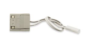
| Quick clip connectors | +2 / +4 mm in width at the joint point | On broken runs | Solder instead of clipping, or house the joint outside the profile |
| Enlarged thermal adhesive | +0.2 / +0.4 mm in height | On high power installations | Verify the remaining useful height under the diffuser |
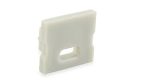
| Power cable exiting | Cable cross-section + passage through the end cap | At the end of each run | Use end caps with dedicated cable gland holes |
The first case is what generates the most returns. An IP65 silicone strip does not have the same width as its IP20 twin: if the profile datasheet declares installable PCBs up to 10 mm, a strip with 10 mm PCB but 12.5 mm outer jacket simply won't fit. For these applications there are specific profiles, such as the 15x10mm aluminum profile for silicone LED strips PR-AC03-00, designed precisely to accommodate the coating.
4. The five thermal classes of profiles
To make the tables in the following chapters immediately usable, we've grouped the profiles into five thermal classes. The classification doesn't replace the individual product datasheet, but it allows you to understand in two seconds whether you're going in the right direction or whether you're about to make a big mistake.
The classification criterion combines three quantities: the cross-sectional area of solid aluminum, the external dissipating surface area per linear meter and the internal chamber height, which determines the air volume around the strip and the distance between LEDs and diffuser.
| Class | Description | Indicative aluminum mass | Max power surface mount | Max power recessed | Max power in closed cabinet |
|---|---|---|---|---|---|
| T1 — Micro | Very thin profiles, minimum cross-section, height ≤ 6 mm | 60-130 g/m | 9.6 W/m | 7.2 W/m | 4.8 W/m |
| T2 — Compact | Standard low profiles, height 7-12 mm | 130-260 g/m | 14.4 W/m | 11.5 W/m | 9.6 W/m |
| T3 — Medium | Generous cross-section profiles, height 13-20 mm | 260-450 g/m | 19.2 W/m | 15.5 W/m | 12.5 W/m |
| T4 — High | Large profiles, double chamber, internal fins | 450-800 g/m | 28 W/m | 22 W/m | 18 W/m |
| T5 — Maximum | Suspended and architectural profiles of large cross-section | > 800 g/m | 40 W/m and above | 32 W/m | — |
Three important clarifications on how to read this table, because it's the key to everything else in the guide.
First: the values refer to profile with diffuser mounted, 25 °C ambient temperature and continuous linear installation. These are already realistic conditions, not laboratory conditions. If you work in a warmer environment or in a more unfavorable configuration you must apply the coefficients from chapter 13.
Second: "surface mount" means profile mounted on wall or ceiling with at least three sides exposed to air. "Recessed" means profile housed in drywall, masonry or cabinet with only the front part free. "Closed cabinet" means profile inside a sealed volume or with negligible air exchange, such as the interior of a wardrobe, a closed showcase or a cove plastered on all sides.
Third: these are prudent thresholds, not absolute breaking limits. Exceeding them doesn't mean the product fails immediately: it means you're eroding the useful life margin and that, if something goes wrong — the environment is warmer than expected, the diffuser is more opaque, the strip always works at 100% — the problem will emerge.
The special case of waterproof profiles
Profiles with a high degree of protection deserve a separate line. The same aluminum cross-section, if sealed with gaskets and sealed diffuser, loses a significant portion of its dissipating capacity because natural convection through the gaps is lost and because the internal air volume is closed and progressively heats up.
| Degree of protection of the solution | Reduction in allowable power | Technical reason | Recommended measure |
|---|---|---|---|
| IP20 open (without diffuser) | Reference 100% | Free convection | Beware of glare and dust |
| IP20 with standard diffuser | −10 / −15% | Partially closed chamber | Value already included in T1-T5 classes |
| IP44-IP54 | −20 / −25% | Partial gaskets, reduced air exchange | Choose a higher thermal class |
| IP65 sealed | −30 / −35% | Sealed chamber, conduction only | Prefer high efficiency strips |
| IP67 / immersion | −40 / −50% | No convection, hot air mass trapped | Limit to powers ≤ 12 W/m unless verified |
This is why the waterproof profiles in the catalog, such as the 21x10mm waterproof aluminum profile PR-SL09-12 and the 21x16mm waterproof aluminum profile PR-SL10-13, have a more generous cross-section than the PCB width alone would require: the extra mass serves precisely to compensate for the loss of convection.
5. Surface mount profile table (SL series)
The SL series collects profiles for surface application on wall, ceiling, furniture or structure. It's the most used family and also the one where the most mistakes are made, because the dimensional variety is wide and the temptation to "take the smallest that fits" is strong.
In the following table you'll find, for each profile, the external dimensions, the maximum PCB width that can be housed, the assigned thermal class and the maximum recommended power in the two most frequent installation conditions. The "Max PCB" field reports the declared value where verified on the datasheet and otherwise the prudent estimate derived from the geometry: before ordering always verify the "Installable PCBs" field on the product page.
| Code | Profile | Dimensions | Max PCB | Class | Max W/m surface | Max W/m recessed or in cabinet | Typical use |
|---|---|---|---|---|---|---|---|
| PR-SL13-02 | 8x5mm aluminum profile | 8 x 5 mm | ~5 mm | T1 | 9.6 | 4.8 | Micro coves, showcases, modeling, signs |
| PR-SL04-04 | 18x6mm foldable profile | 18 x 6 mm | ~12 mm | T1 | 9.6 | 7.2 | Curves, shapes, non-straight lines |
| PR-SL03-02 | 10x8mm aluminum profile | 10 x 8 mm | ~6 mm | T1 | 9.6 | 7.2 | Furniture, thin shelves, niches |
| PR-SL12-16 | 13x8mm aluminum profile | 13 x 8 mm | ~8 mm | T2 | 14.4 | 9.6 | Kitchens, under-cabinet, furnishing |
| PR-SL20-20 | 15x11mm aluminum profile | 15 x 11 mm | ~10 mm | T2 | 14.4 | 11.5 | General compact use |
| PR-SL17-03 | 17x7mm aluminum profile | 17 x 7 mm | ~12 mm | T2 | 14.4 | 11.5 | Low surface lines, backlighting |
| PR-SL08-03 | 17x8mm aluminum profile | 17 x 8 mm | 12 mm (declared) | T2 | 14.4 | 11.5 | The best seller: universal surface use |
| PR-SL16-16 | 13x13mm aluminum profile | 13 x 13 mm | ~8 mm | T2 | 14.4 | 11.5 | Tall chamber, excellent light mix |
| PR-SL14-16 | 13x12mm aluminum profile | 13 x 12 mm | ~8 mm | T2 | 14.4 | 11.5 | Furnishing, tall chamber in little space |
| PR-SL09-12 | 21x10mm waterproof profile | 21 x 10 mm | ~14 mm | T2 (IP) | 11.5 | 9.6 | Bathrooms, protected outdoors, professional kitchens |
| PR-SL15-01 | 21x13mm aluminum profile | 21 x 13 mm | ~16 mm | T3 | 19.2 | 15.5 | Wide RGBW strips, high density |
| PR-SL05-03 | 17x15mm aluminum profile | 17 x 15 mm | ~12 mm | T3 | 19.2 | 15.5 | Deep chamber, excellent anti-dotting |
| PR-SL10-13 | 21x16mm waterproof profile | 21 x 16 mm | ~14 mm | T3 (IP) | 14.4 | 12 | Outdoors, humid environments, medium powers |
| PR-SL11-01 | 21x17mm aluminum profile | 21 x 17 mm | ~16 mm | T3 | 19.2 | 15.5 | Continuous medium power lines |
| PR-SL06-05 | 12x27mm aluminum profile | 12 x 27 mm | ~8 mm | T3 | 19.2 | 15.5 | Tall and narrow, grazing light on wall |
| PR-SL07-05 | 27x7mm aluminum profile | 27 x 7 mm | ~20 mm | T3 | 19.2 | 15.5 | Wide strips or double row, reduced thickness |
| PR-SL01-01 | 21x25mm aluminum profile | 21 x 25 mm | ~16 mm | T4 | 28 | 22 | High power, offices, retail, long lines |
| PR-SL02-06 | 36x26mm aluminum profile | 36 x 26 mm | ~30 mm | T4 | 28 | 22 | Double row, high power, technical environments |
| PR-SL18-25 | 35x35mm aluminum profile | 35 x 35 mm | ~30 mm | T5 | 40 | 32 | Architectural, high power, great heights |
| PR-AC03-00 | 15x10mm profile for silicone strips | 15 x 10 mm | Seat for jacket | T2 | 11.5 | 9.6 | IP65/IP67 strips coated in silicone |
| PR-SL21-00 | Polycarbonate tubular profile | Tubular | See datasheet | Non-metallic | 4.8 | 4.8 | Only low powers: polycarbonate doesn't dissipate |
The last row is the one we invite you to pause on. The polycarbonate tubular profile is not a heat sink: it's a container. It's fine for 4.8 W/m strips in decorative or temporary applications, but it shouldn't be used as an alternative to aluminum in fixed medium or high power installations. It's a distinction that generalist catalogs tend not to highlight and that instead radically changes the long-term result.
How to read the "surface" and "recessed" columns of the SL series
Many surface profiles end up, in practice, recessed inside a cabinet or inside a cove. It's perfectly legitimate, but it changes the reference column. A PR-SL08-03 mounted under a kitchen cabinet, with air circulating freely, works at 14.4 W/m without problems. The same profile embedded inside a wooden box closed on three sides must be treated as a cabinet installation, therefore with the limit of 9.6-11.5 W/m.
This is the single measure that, applied consistently, eliminates most complaints. You don't need to change the product: you need to change the table row you're reading.
6. Recessed profile table (RE series)
Recessed profiles are designed to be embedded in the structure: drywall, wood, masonry, furniture. They by definition have a more unfavorable thermal condition than their surface-mounted counterparts, because the side walls and bottom are in contact with insulating materials and the only real dissipating surface is the front one, often already occupied by the diffuser.
For this family, therefore, the column that counts is almost always the "recessed" one. The "surface" column only makes sense in the rare cases where the profile is used resting or in hybrid configurations.
| Code | Profile | Dimensions | Max PCB | Class | Max W/m recessed | Max W/m in closed cove | Typical use |
|---|---|---|---|---|---|---|---|
| PR-RE09-0222 | 8x9mm recessed profile | 8 x 9 mm | ~5 mm | T1 | 7.2 | 4.8 | Minimal routings in wood, custom furniture |
| PR-RE14-23 | 15x8mm recessed profile | 15 x 8 mm | ~10 mm | T2 | 11.5 | 9.6 | Thin recesses, furnishing |
| PR-RE15-16 | 17x8mm recessed profile | 17 x 8 mm | ~10 mm | T2 | 11.5 | 9.6 | Standard compact recess |
| PR-RE10-02 | 21x9mm recessed profile | 21 x 9 mm | ~12 mm | T2 | 11.5 | 9.6 | Recess with mounting flanges |
| PR-RE01-03 | 23x8mm recessed profile | 23 x 8 mm | ~12 mm | T2 | 11.5 | 9.6 | The classic drywall recess |
| PR-RE01B-03 | 23x8mm recessed profile without groove | 23 x 8 mm | ~12 mm | T2 | 11.5 | 9.6 | Variant for flush finishes |
| PR-RE11-16 | 17x12mm recessed profile | 17 x 12 mm | ~10 mm | T2 | 12 | 9.6 | Deeper chamber, softer light |
| PR-RE13-23 | 12x21mm recessed profile | 12 x 21 mm | ~8 mm | T3 | 15.5 | 12.5 | Narrow and deep, controlled beams |
| PR-RE12-16 | 17x17mm recessed profile | 17 x 17 mm | ~10 mm | T3 | 15.5 | 12.5 | Good output-dissipation compromise |
| PR-RE02-03 | 23x15mm recessed profile | 23 x 15 mm | ~12 mm | T3 | 15.5 | 12.5 | Medium power recess |
| PR-RE05-01 | 32x15mm recessed profile | 32 x 15 mm | ~20 mm | T3 | 16 | 13 | Wide strips or double row recessed |
| PR-RE03-05 | 37x15mm recessed profile | 37 x 15 mm | ~24 mm | T4 | 22 | 18 | Professional linear recesses |
| PR-RE06-01 | 25x32mm recessed profile | 25 x 32 mm | ~16 mm | T4 | 22 | 18 | Great depth, excellent optical control |
| PR-RE04-07 | 22x67mm recessed profile | 22 x 67 mm | ~16 mm | T5 | 32 | 26 | Deep recess, high power, offices |
| PR-RE07-12 | 29x8mm waterproof recessed profile | 29 x 8 mm | ~14 mm | T2 (IP) | 9.6 | 7.2 | Recesses in humid environments |
| PR-RE08-13 | 29x14mm waterproof recessed profile | 29 x 14 mm | ~14 mm | T3 (IP) | 12 | 9.6 | Bathrooms, spas, covered outdoors |
| PR-RE16-00 | Opaque 3m LED bar with preassembled 7W/m COB strip | Complete bar | Preassembled | T2 | 7 (standard) | 7 | Turnkey solution, zero matching errors |
The final row deserves operational attention. Preassembled bars completely eliminate the risk of wrong matching: profile, strip, diffuser and wiring arrive already paired and verified. On sites with many repetitive meters, or when installation is entrusted to different crews, they are often the most rational choice in terms of man-hours and risk of dispute.
The 10 millimeter air rule
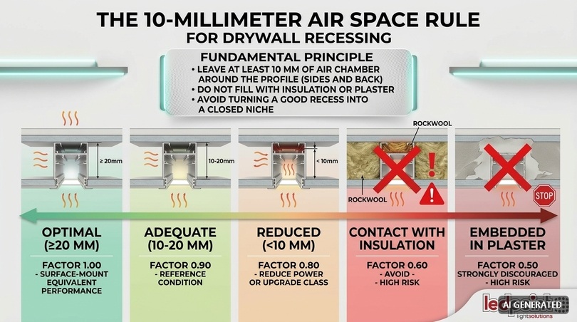
In drywall recessing there's a practical rule worth formalizing: leave at least 10 mm of air chamber around the profile body, on the sides and on the back, and never fill the space with rock wool, polyurethane foam or plaster in contact. Insulating material in direct contact with the aluminum cancels the dissipating function and turns a correct recess into a closed cove.
| Recess configuration | Air chamber around profile | Correction factor on power | Expected outcome |
|---|---|---|---|
| Profile free with ≥ 20 mm air on three sides | Large | 1.00 | Almost surface behavior |
| Profile with 10-20 mm air | Adequate | 0.90 | Reference condition of the tables |
| Profile with < 10 mm air | Reduced | 0.80 | Reduce power or move up a class |
| Profile in contact with insulator | None | 0.60 | High risk: to be avoided |
| Profile embedded in plaster on all sides | None | 0.50 | Strongly discouraged configuration |
7. Angular profile table (AN series)
45° or 90° angular profiles are the mandatory choice when illuminating a work surface from above, when you want to graze a wall starting from the ceiling, or when hiding the source inside a corner. From a thermal point of view they have a structural advantage: resting on two surfaces instead of one, they have one more conduction path, and this makes them slightly more performant than the cross-section alone would suggest — provided they rest on conductive material, which doesn't happen with drywall.
| Code | Profile | Dimension | Max PCB | Class | Max W/m surface | Max W/m in cabinet | Typical emission angle |
|---|---|---|---|---|---|---|---|
| PR-AN06-20 | 10mm angular profile | 10 mm side | ~6 mm | T1 | 9.6 | 4.8 | 45° towards the surface |
| PR-AN02-08 | 16mm angular profile | 16 mm side | ~10 mm | T2 | 14.4 | 9.6 | 45°, the most used under cabinet |
| PR-AN03-08 | 16mm angular profile with rear groove | 16 mm side | ~10 mm | T2 | 14.4 | 9.6 | 45° with integrated cable passage |
| PR-AN07-03 | 18x18mm angular profile | 18 x 18 mm | ~12 mm | T2 | 14.4 | 11.5 | 45°, enlarged version |
| PR-AN01-03 | 19x19mm hollow angular profile | 19 x 19 mm | ~12 mm | T3 | 19.2 | 12.5 | 45° with large internal chamber |
| PR-AN04-09 | 30mm angular profile | 30 mm side | ~20 mm | T4 | 28 | 18 | 45°, large surfaces and high powers |
| PR-AN05-09 | 30mm angular profile with rear groove | 30 mm side | ~20 mm | T4 | 28 | 18 | 45° with cable management |
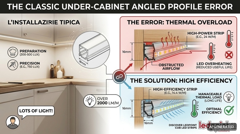
The classic mistake of the angular under cabinet
The most frequent installation of the 16 mm angular profile is under the kitchen cabinet, above the work surface. It's an application where the UNI EN 12464-1 standard suggests illuminance levels on the work surface in the order of 300-500 lux for domestic preparation activities and up to 750 lux for precision work, and where the client typically asks for "lots of light".
The temptation is to insert a 19.2 or 24 W/m strip to be sure not to fall short. Don't do it on a 16 mm angular without verifying ventilation. The profile is often screwed under the bottom of the cabinet, with the upper part in contact with the wood and the front part facing downward: natural convection, which carries hot air upward, is hindered. In that condition the realistic limit is that of the "in cabinet" column, i.e. 9.6 W/m.
The correct solution is not to reduce the light: it's to use a high-efficiency strip. With a 155 lm/W product at 14.4 W/m you get about 2,000 lm/m, more than enough for a work surface, with manageable thermal load. You'll find them in the 14.4 W/m LED strips section and in the Ledpoint COB LED strips line.
8. Wall mount and dual emission profile table (WL series)
Wall profiles are designed to create a visible architectural light line, often with emission upward and downward simultaneously. They generally have generous cross-sections, which makes them thermally comfortable, but they introduce a specific problem: in dual emission versions the total power is the sum of the two strips, and the heat concentrates in the same body.
| Code | Profile | Dimensions | Max PCB per seat | Seats | Class | Max total W/m | Max W/m per seat |
|---|---|---|---|---|---|---|---|
| PR-WL01-03 | 48x18mm wall profile | 48 x 18 mm | ~12 mm | 1 | T4 | 28 | 28 |
| PR-WL02-03 | 24x24mm wall profile | 24 x 24 mm | ~16 mm | 1 | T3 | 19.2 | 19.2 |
| PR-WL03-01 | 29x30mm wall profile | 29 x 30 mm | ~20 mm | 1 | T4 | 28 | 28 |
| PR-WL05-05 | 34x34mm wall profile | 34 x 34 mm | ~24 mm | 1 | T5 | 40 | 40 |
| PR-WL04-05 | 70x31mm wall dual emission profile | 70 x 31 mm | ~20 mm | 2 | T5 | 44 | 22 per side |
| PR-WALL9242 | 92x42mm white painted wall profile | 92 x 42 mm | ~30 mm | 1-2 | T5 | 50 | 25 per side |
On dual emission a rule we often repeat to designers applies: don't think per single strip, think in total watts per meter of profile. Two 14.4 W/m strips in a dual emission profile mean 28.8 W/m of heat concentrated in a single aluminum body. The profile can handle them, but you're already close to its operating limit: if you then install it in a narrow niche close to the wall, the derating from lack of air circulation takes you out of specification.
Painted profiles: a note that surprises many
White or black painted profiles, aesthetically preferred in many projects, have a slightly different thermal behavior than natural anodized aluminum. Powder coating adds a layer of a few tens of microns that marginally reduces conduction to the outside but increases the surface emissivity, favoring radiative exchange. Overall the net effect is modest and generally negligible: it's not a reason to give up the desired finish. Different is the case of black, which absorbs more incident radiation and in installations exposed to direct sunlight can start from a higher base temperature.
9. Drywall profile table (DW series)
The DW series is the technically most delicate one, and not for dimensional reasons. Drywall profiles are designed to be plastered and skimmed together with the board, with the flanges embedded in the material. This produces the cleanest aesthetic result that exists (the light seems to come out of the wall without a frame) but creates the worst thermal condition among all those addressed so far.
In the following table the determining column is therefore the maximum power in plastered configuration. The "ventilated installation" column only applies if the back of the profile faces a cavity with real air exchange.
| Code | Profile | Dimensions | Max PCB | Class | Max W/m plastered | Max W/m with ventilated back | Type |
|---|---|---|---|---|---|---|---|
| PR-DW06-02 | 50x10mm drywall profile | 50 x 10 mm | ~12 mm | T2 | 9.6 | 11.5 | Flush, direct light |
| PR-DW08-03 | 57x10mm drywall profile | 57 x 10 mm | ~12 mm | T2 | 9.6 | 11.5 | Flush, wide flanges |
| PR-DW15-03 | 38x11mm drywall profile | 38 x 11 mm | ~10 mm | T2 | 9.6 | 11.5 | Compact flush |
| PR-DW07-01 | 62x12mm drywall profile | 62 x 12 mm | ~14 mm | T2 | 11.5 | 13 | Flush, large surface |
| PR-CR4412 | 44x12mm profile with drywall | 44 x 12 mm | ~12 mm | T2 | 11.5 | 13 | Flush, economic version |
| PR-DW01-03 | 16x12mm angular drywall profile | 16 x 12 mm | ~10 mm | T2 | 9.6 | 11.5 | Internal corner |
| PR-DW02-03 | 64x22mm angular drywall profile | 64 x 22 mm | ~14 mm | T3 | 13 | 15.5 | Angular cove |
| PR-DW16-03 | 54x32mm cove profile | 54 x 32 mm | ~14 mm | T3 | 15.5 | 18 | Perimeter cove |
| PR-DW14-03 | 36x34mm drywall profile | 36 x 34 mm | ~12 mm | T3 | 15.5 | 18 | Deep cove |
| PR-DW03-03 | 42x32mm drywall profile | 42 x 32 mm | ~14 mm | T3 | 15.5 | 18 | Deep cove, indirect light |
| PR-DW11-03 | 72x31mm drywall profile | 72 x 31 mm | ~16 mm | T4 | 18 | 22 | Large cove |
| PR-DW04-06 | 35x49mm drywall profile | 35 x 49 mm | ~14 mm | T4 | 18 | 22 | Tall cove, wall washer |
| PR-DW10-05 | 54x47mm drywall profile | 54 x 47 mm | ~16 mm | T4 | 18 | 22 | Tall and wide cove |
| PR-DW05-07 | 50x49mm drywall profile | 50 x 49 mm | ~16 mm | T4 | 18 | 22 | Tall cove, dual function |
| PR-DW09-01 | 97x35mm drywall profile | 97 x 35 mm | ~20 mm | T5 | 24 | 30 | Large cross-section, high powers |
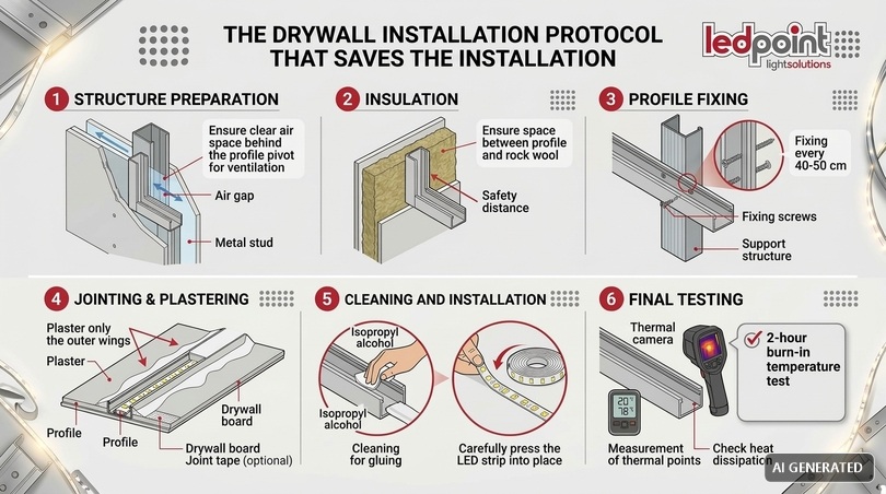
The drywall installation protocol that saves the installation
On this family more than any other, the difference between a job that lasts and one that comes back under warranty lies in the installation protocol, not in the product. Here are the points to respect, in order of importance.
| Phase | What to do | What never to do | Why |
|---|---|---|---|
| Structure preparation | Provide ≥ 20 mm free behind the profile | Fix the profile directly to the framework | An air volume is needed behind the back |
| Insulation | Set back rock wool by at least 30 mm | Bring the insulator into contact with aluminum | The insulator cancels dissipation |
| Profile fixing | Screws every 40-50 cm, without deforming the flanges | Tighten until bending the body | Deformation reduces strip adhesion |
| Plastering | Plaster only the flanges, never the seat | Fill the chamber with plaster | Plaster closes the chamber and retains heat |
| Strip installation | Install after plastering and complete drying | Install before construction work | Residual moisture and dust compromise the adhesive |
| Seat cleaning | Degrease with isopropyl alcohol | Glue on gypsum dust | Without full contact there's no thermal transfer |
| Painting | Mask the seat with tape | Paint the inside of the profile | Paint reduces reflection and contact |
| Testing | Test at regime after 2 hours of operation | Test cold after 5 minutes | Overtemperatures emerge at regime |
The last row is the most valuable advice in this chapter. An overloaded strip is fine for the first few minutes. The verification must be done after at least two hours of continuous operation, placing the back of your hand on the profile: if you can't keep it pressed for more than a few seconds, you're over 55-60 °C surface temperature and almost certainly over the design limits. It's a crude test but surprisingly reliable, and anyone can do it without instrumentation.
10. Suspended profile table (CL series)
The CL series suspended profiles are the most generous in the catalog. They're designed to create suspended linear lighting fixtures, typically in offices, open spaces, showrooms, gyms and commercial environments where high flows and line continuity over tens of meters are needed.
Thermally they're the most relaxed: suspended in empty space, with air circulating on all sides and significant aluminum cross-sections. The constraint here is almost never heat: it's voltage drop and power supply sizing.
| Code | Profile | Dimensions | Max PCB | Class | Max W/m suspended | Max W/m ceiling mount | Use |
|---|---|---|---|---|---|---|---|
| PR-CL01-06 | 36x75mm aluminum profile | 36 x 75 mm | ~28 mm | T5 | 45 | 36 | Offices, open spaces, continuous lines |
| PR-CL02-07 | 50x75mm aluminum profile | 50 x 75 mm | ~40 mm | T5 | 55 | 44 | Double row, high power, retail |
| PR-CL04-18 | 60x73mm aluminum profile | 60 x 73 mm | ~48 mm | T5 | 60 | 48 | Industrial and sports lighting |
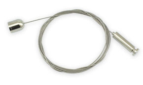
For suspended mounting you need Ledpoint suspension cables, while for continuous lines beyond the bar length profile joints are essential, which guarantee alignment and optical continuity avoiding the "step" effect at the joint point.
Why long suspended lines are powered from the center
On a 12 meter suspended line, powering from one end means that the last meter receives a voltage sensibly lower than the first, with a perceptible brightness difference and, on white strips, even a slight chromatic difference. Powering from the center halves the length of each branch and reduces the voltage drop to a quarter, because the drop grows with the square of the length for the same distributed current.
On professional installations the even better solution is to switch to 48V LED strips, which for the same power circulate a quarter of the current compared to 12V and allow much longer runs without re-feeding.
11. Walkable, ceramic, stair and skirting board profile table
This is the family where mechanical constraints weigh as much as thermal ones. A walkable profile must resist load, guarantee water and dust tightness, and in the case of outdoor floors withstand freeze-thaw cycles. The strip, for its part, must be chosen with adequate IP rating and contained power, because embedding in screed or tile adhesive eliminates any convection.
| Code | Profile | Dimensions | Max PCB | Class | Recommended max W/m | Strip requirement | Application |
|---|---|---|---|---|---|---|---|
| PR-TI02-10 | 8mm ceramic cladding profile | For 8 mm tile | ~8 mm | T1 | 7.2 | IP20 or IP65 | Vertical cladding |
| PR-TI03-10 | 11mm ceramic cladding profile | For 11 mm tile | ~10 mm | T2 | 9.6 | IP20 or IP65 | Cladding, shower niches |
| PR-TI01-11 | 12mm walkable waterproof ceramic floor profile | For 12 mm tile | ~10 mm | T2 (IP) | 7.2 | IP65 minimum | Indoor and outdoor floors |
| PR-FL01-21 | 20x11mm walkable floor profile | 20 x 11 mm | ~12 mm | T2 (IP) | 9.6 | IP65/IP67 | Paths, step markers |
| PR-FL03-21 | 25x11mm walkable floor profile | 25 x 11 mm | ~14 mm | T2 (IP) | 9.6 | IP65/IP67 | Wide paths, showrooms |
| PR-FL02-21 | 20x26mm walkable floor profile | 20 x 26 mm | ~12 mm | T3 (IP) | 12 | IP65/IP67 | Deep recess, outdoors |
| PR-ST01-00 | 30x27mm stair profile | 30 x 27 mm | ~16 mm | T3 | 15.5 | IP20 indoor | Stair risers, safety |
| PR-BB02-02 | 75x13mm skirting board profile | 75 x 13 mm | ~12 mm | T3 | 13 | IP20 | Luminous skirting board |
| PR-CC01-06-G3 | PVC profile for concrete | To be embedded | See datasheet | Non-metallic | 4.8 | IP65/IP67 | Formwork in casting |
Two specific warnings on this family, both resulting from real problems seen on site.
On stairs, never exceed 400-500 lm/m on the riser. The value is not dictated by heat but by glare: a too powerful strip on a riser produces excessive contrast in the visual field of someone descending, with a counterproductive effect on safety. UNI EN 12464-1 addresses the issue of discomfort glare precisely in relation to paths and stairs.
In concrete casting and tile adhesive use exclusively strips with adequate IP rating and soldered and sealed connections. Clip joints are not admissible in these applications: moisture infiltration at the contact point produces electrolytic corrosion of the copper traces, which manifests months later with progressive shutdown of sections. For these works solder joints for LED strips are more suitable.
12. Round profile and special application table
The NE series round profiles are born to reproduce the aesthetic of the continuous luminous tube with the mechanics and dissipation of aluminum. They're particularly suitable for decorative suspensions, retail and architectural projects in which the circular cross-section is part of the formal language.
| Code | Profile | Diameter | Max PCB | Class | Max W/m | Notes |
|---|---|---|---|---|---|---|
| PR-NE01-14 | Ø30mm round profile | 30 mm | ~16 mm | T3 | 19.2 | Decorative suspensions |
| PR-NE02-15 | Ø30mm waterproof round profile | 30 mm | ~16 mm | T3 (IP) | 13 | Outdoors and humid environments |
| PR-NE04-19 | Ø50mm round profile | 50 mm | ~30 mm | T4 | 28 | Large environments, double strip |
| PR-NE03-17 | Ø75mm round profile | 75 mm | ~45 mm | T5 | 40 | Architectural, high powers |
Furniture profiles: shelves, wardrobes, mirrors, handrails
The furniture segment has a dominant rule that precedes all others: space is almost always enclosed. A wardrobe, a drawer, a showcase, the cavity behind a mirror are volumes with minimal air exchange, in which the internal ambient temperature progressively rises during operation. For this reason, on this family, the reference column is always the most conservative one.
| Code | Profile | Application | Max PCB | Recommended max W/m | Design note |
|---|---|---|---|---|---|
| PR-SH01-03 | Shelf profile | Illuminated shelves | ~10 mm | 9.6 | Verify shelf thickness |
| PR-SH02-03 | 18mm shelf dual emission profile | Shelves, dual emission | ~10 mm | 2 x 7.2 | Sum the watts of the two strips |
| PR-SH03-03 | 25mm shelf dual emission profile | Thick shelves | ~12 mm | 2 x 9.6 | Suitable for 25 mm shelves |
| PR-WB01-00 | 15x29mm wardrobe profile | Inside wardrobes and cabins | ~10 mm | 9.6 | Enclosed space: stay low |
| PR-MR01-03 | Mirror profile | Mirrors, bathrooms | ~10 mm | 9.6 | Prefer CRI ≥ 90 for face |
| PR-HR01-0203 | Illuminated aluminum handrail | Stairs, accessible paths | ~10 mm | 9.6 | Hand contact: limit temperature |
The last row contains a constraint that is neither aesthetic nor durability-related, but user safety: a handrail is touched. The surface temperature of an element destined for prolonged contact with skin must not be uncomfortable, and this imposes a power limit more stringent than what the aluminum cross-section alone would allow. In practice, on an illuminated handrail it's advisable to stay well below 10 W/m and favor high-efficiency strips.
For mirrors, instead, the decisive variable is not power but color rendering: in front of a mirror one applies makeup, shaves, evaluates one's skin color. A CRI below 90 produces unsatisfactory skin tone rendering and generates complaints that have nothing to do with lumens. It's worth orienting towards high-rendering lines like Sunlike LED strips.
```html
13. Correction coefficients: diffuser, recessed, IP, temperature
The tables in the previous chapters provide a starting value. The actual allowable value for your site is obtained by multiplying that value by a series of coefficients that account for the actual conditions. It's the same approach you've always used for cable capacity: tabular value, then correction factors for temperature, grouping, and installation.
The operational formula is simple:
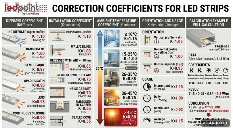
Allowable W/m = Table W/m × Kdiffuser × Kinstallation × Kambient × Korientation × Kusage
Diffuser coefficient (K diffuser)
| Diffuser type | K diffuser | Thermal effect | When to use it |
|---|---|---|---|
| No diffuser (open profile) | 1.10 | Maximum convection | Only where LEDs are not in the field of view |
| Transparent diffuser | 1.00 | Reference | Maximum output, visible LED points |
| Semi-opaque diffuser | 0.97 | Negligible | Good output-uniformity compromise |
| Opaque diffuser | 0.95 | Slight heat retention | High uniformity, hidden points |
| Satin diffuser | 0.95 | Slight heat retention | Soft effect |
| Lens diffuser | 0.98 | Negligible | Controlled beam |
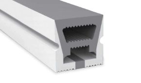
| Continuous silicone diffuser | 0.90 | Insulating, sealed chamber | Curved lines, neon effect |
Installation coefficient (K installation)
| Installation condition | K installation | Concrete example |
|---|---|---|
| Suspended, air on all sides | 1.10 | CL profile hanging in open space |
| Surface mounted on wall or ceiling | 1.00 | PR-SL08-03 on wall |
| Recessed with air chamber ≥ 10 mm | 0.85 | PR-RE01-03 in ventilated false ceiling |
| Recessed without air chamber | 0.75 | DW profile plastered in contact |
| Inside closed cabinet | 0.70 | PR-WB01-00 in wardrobe |
| Embedded in screed or adhesive | 0.65 | PR-TI01-11 under tile |
| Completely sealed cove | 0.55 | Cove plastered on all sides |
Ambient temperature coefficient (K ambient)
Thermal classes are calibrated for 25 °C. Every real situation deviates from this, and in some cases dramatically: a false ceiling under an uninsulated roof, in summer, can exceed 45 °C, and a showcase exposed to the sun with other light sources inside can reach similar values.
| Operating ambient temperature | K ambient | Typical context |
|---|---|---|
| ≤ 10 °C | 1.15 | Cold rooms, winter outdoors |
| 15-25 °C | 1.00 | Climate-controlled environments, reference |
| 26-35 °C | 0.88 | Kitchens, technical rooms, summer without AC |
| 36-45 °C | 0.75 | Attic false ceilings, sunny showcases |
| > 45 °C | 0.60 | Verify the strip's operating limit |
Attention: many strips declare an operating temperature range from −10 °C to +45 °C. Beyond that threshold, you are not just reducing useful life: you are working out of specification, with warranty voidance.
Orientation and usage coefficient
| Factor | Condition | Coefficient | Explanation |
|---|---|---|---|
| K orientation | Vertical profile on wall | 1.05 | Convective motion grazes the entire section |
| K orientation | Horizontal ceiling profile, downward emission | 1.00 | Reference condition |
| K orientation | Horizontal profile with upward emission | 0.95 | Heat stagnates in the chamber |
| K usage | Intermittent operation (< 4 h/day) | 1.10 | The body has time to cool down |
| K usage | Operation 8-12 h/day | 1.00 | Commercial reference |
| K usage | Continuous 24/7 operation | 0.92 | No cooling window |
| K usage | Average dimming < 70% | 1.15 | Actual power lower than nominal |
Complete calculation example
Let's see it applied to a concrete case, the most frequent one in homes.
| Data | Value | Source |
|---|---|---|
| Chosen profile | PR-RE01-03 recessed 23x8mm | Project |
| Table value (recessed) | 11.5 W/m | Chapter 6 |
| K diffuser (opaque) | 0.95 | Table 13.1 |
| K installation (recessed with chamber ≥ 10 mm) | 0.85 | Table 13.2 |
| K ambient (climate-controlled living room) | 1.00 | Table 13.3 |
| K orientation (ceiling, downward emission) | 1.00 | Table 13.4 |
| K usage (5 hours a day) | 1.00 | Table 13.4 |
| Result | 11.5 × 0.95 × 0.85 = 9.3 W/m | Calculation |
The operational conclusion is clear: on that profile, in that configuration, the 9.6 W/m strip is at the limit and the 14.4 W/m strip is out. If more lumens are needed, the way forward is not to increase watts: it's to change the strip by choosing a high-efficiency one, or to move to a higher class profile like the PR-RE02-03 23x15mm.
14. High efficiency strips: how the rules change
This is the chapter that, in our experience, changes an installer's way of working the most. Luminous efficiency, measured in lumens per watt (lm/W), is the ratio between the light produced and the power absorbed. It is the parameter that decides how many watts you must burn to achieve the required lighting result, and therefore it is the parameter that also decides which profile you can afford.
Today's market offers, in the same price range as a few years ago, products with very different efficiencies. A concrete and documented example from the catalog: a 2835 strip with 240 leds/m at 24V and 14.4 W/m can deliver about 2,000 lm/m with an efficiency of around 155 lm/W, while a 2835 strip with 120 leds/m with the exact same 14.4 W/m power delivers about 1,410 lm/m with an efficiency of around 110 lm/W. Same power, same heat, over 40% more light.
Table: how many watts are needed to get the required lumens
| Required lumens/meter | With 80 lm/W strip | With 110 lm/W strip | With 140 lm/W strip | With 160 lm/W strip | With 180 lm/W strip |
|---|---|---|---|---|---|
| 500 lm/m | 6.3 W/m | 4.5 W/m | 3.6 W/m | 3.1 W/m | 2.8 W/m |
| 800 lm/m | 10.0 W/m | 7.3 W/m | 5.7 W/m | 5.0 W/m | 4.4 W/m |
| 1,000 lm/m | 12.5 W/m | 9.1 W/m | 7.1 W/m | 6.3 W/m | 5.6 W/m |
| 1,400 lm/m | 17.5 W/m | 12.7 W/m | 10.0 W/m | 8.8 W/m | 7.8 W/m |
| 2,000 lm/m | 25.0 W/m | 18.2 W/m | 14.3 W/m | 12.5 W/m | 11.1 W/m |
| 2,500 lm/m | 31.3 W/m | 22.7 W/m | 17.9 W/m | 15.6 W/m | 13.9 W/m |
| 3,000 lm/m | 37.5 W/m | 27.3 W/m | 21.4 W/m | 18.8 W/m | 16.7 W/m |
| 4,000 lm/m | 50.0 W/m | 36.4 W/m | 28.6 W/m | 25.0 W/m | 22.2 W/m |
Read the table horizontally and you immediately see the advantage. To get 2,000 lm/m you need 25 W/m with a poor product and 11.1 W/m with an excellent product. In the first case you need a T4 class profile; in the second you get by with a compact T2 like the PR-SL08-03, which costs less, hides better, and installs faster.
The table that crosses efficiency and profile class
Here is the synthetic decision-making tool. In the row, the required lumens per meter; in the column, the efficiency of the chosen strip; in the cell, the minimum profile class required for surface installation with a diffuser.
| Required lumens/m | 80 lm/W strip | 110 lm/W strip | 140 lm/W strip | 160 lm/W strip | 180 lm/W strip |
|---|---|---|---|---|---|
| 500 | T1 | T1 | T1 | T1 | T1 |
| 800 | T2 | T1 | T1 | T1 | T1 |
| 1,000 | T2 | T1 | T1 | T1 | T1 |
| 1,400 | T3 | T2 | T2 | T1 | T1 |
| 2,000 | T4 | T3 | T2 | T2 | T2 |
| 2,500 | T5 | T4 | T3 | T3 | T2 |
| 3,000 | T5 | T4 | T4 | T3 | T3 |
| 4,000 | Not recommended | T5 | T5 | T4 | T4 |
This table can also be read in reverse, and that's how it becomes a commercial tool. If the client has already chosen the profile (because the designer mandates it, because it's the one that fits the existing cove, because it's the one in stock) the table tells you how many lumens you can realistically achieve and with which strip class. It becomes the way to technically justify choosing a higher-end product instead of the cheaper one.
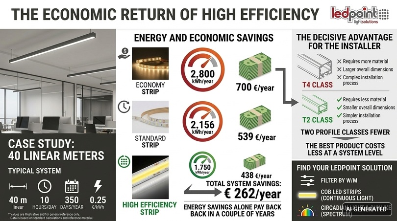
The economic return of high efficiency
It's worth quantifying this, because it's a sales argument that holds up to spreadsheet scrutiny. Let's take a 40 linear meter installation, turned on 10 hours a day for 350 days a year, with an energy cost of €0.25/kWh.
| Scenario | Efficiency | W/m for 2,000 lm/m | Total power | Annual consumption | Annual energy cost | Required profile class |
|---|---|---|---|---|---|---|
| Economy strip | 100 lm/W | 20.0 | 800 W | 2,800 kWh | €700 | T4 |
| Standard strip | 130 lm/W | 15.4 | 616 W | 2,156 kWh | €539 | T3 |
| High efficiency strip | 160 lm/W | 12.5 | 500 W | 1,750 kWh | €438 | T2 |
| Economic difference - high efficiency | — | −37.5% | −300 W | −1,050 kWh | −€262/year | Two classes lower |
The energy savings alone typically pay for the higher cost of the strip in a couple of years. But the decisive advantage, for the installer, is in the last column: two lower profile classes mean lower material costs, smaller footprints, and simpler installation. It's a rare case where the better product costs less at the system level.
In the Ledpoint catalog, high-efficiency lines are quickly identified: the LED strips by power section allows filtering by W/m, while the COB LED strips section collects continuous light products without dotting, and the Circadian Light and Sunlike lines cover applications where spectrum quality matters as much as light quantity.
15. From required lux to the right profile: application table
So far we have reasoned in lumens per meter. But the client doesn't think in lumens: they think "I want to see well", and the designer thinks in lux on the useful plane. This table bridges the two quantities, starting from the illuminance values indicated by UNI EN 12464-1 for indoor workplaces and design practice for residential environments.
| Application | Target lux on plane | Indicative lumens/m | Recommended efficiency | Resulting W/m | Minimum profile class | Recommended profiles |
|---|---|---|---|---|---|---|
| Ambient light, perimeter cove | 50-100 | 300-500 | ≥ 120 lm/W | 2.5-4.8 | T1 | PR-SL03-02, PR-RE09-0222 |
| Step markers and stairs | 100-150 | 300-500 | ≥ 120 lm/W | 2.5-4.8 | T1-T2 | PR-ST01-00, PR-FL01-21 |
| Living room indirect lighting | 100-200 | 600-900 | ≥ 130 lm/W | 5-7.5 | T2 | PR-SL08-03, PR-RE01-03 |
| Kitchen under-cabinet | 300-500 | 1,200-1,800 | ≥ 140 lm/W | 9-13 | T2 | PR-AN02-08, PR-SL12-16 |
| Bathroom mirror | 300-500 | 1,000-1,500 | ≥ 130 lm/W, CRI ≥ 90 | 8-11.5 | T2 | PR-MR01-03, PR-SL08-03 |
| Retail, merchandise display | 500-750 | 1,800-2,600 | ≥ 140 lm/W, CRI ≥ 90 | 13-19 | T3 | PR-SL11-01, PR-SL15-01 |
| Office, general lighting | 500 | 2,000-3,000 | ≥ 150 lm/W | 13-20 | T3-T4 | PR-CL01-06, PR-SL01-01 |
| Office, precision tasks | 750-1,000 | 3,000-4,000 | ≥ 160 lm/W | 19-25 | T4-T5 | PR-CL02-07, PR-SL18-25 |
| Laboratories and workshops | 500-1,000 | 2,500-4,000 | ≥ 150 lm/W | 17-27 | T4-T5 | PR-CL04-18, PR-CL02-07 |
| Showcases and displays | 1,000-2,000 | 3,000-5,000 | ≥ 150 lm/W, CRI ≥ 95 | 20-33 | T4-T5 | PR-SL18-25, PR-NE03-17 |
| Museum lighting | 50-200 (controlled) | 300-800 | CRI ≥ 95, low UGR | 2.5-6 | T1-T2 | PR-RE12-16, PR-SL05-03 |
| Exterior architectural | Variable | 1,000-2,500 | ≥ 140 lm/W, IP65+ | 7-18 | T3 (IP) | PR-SL10-13, PR-NE02-15 |
The indicated lumens per meter are first-approximation values valid for coves and lines placed at a typical distance from the useful plane (2.5-3 m for the ceiling, 0.5-0.7 m for under-cabinet). For precise sizing, each profile datasheet in the catalog provides a specific lux calculation tool for the installation, which accounts for the actual geometry.
16. Neon flex and dedicated profiles: compatibility tables
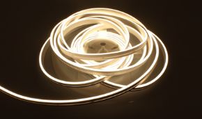
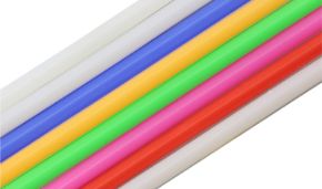
Neon flex, or flexible LED tube, plays by different rules. It is not a strip to be inserted into a profile: it is a complete product, in which the strip is embedded in a PVC or silicone body that acts as a diffuser, mechanical protection, and aesthetic coating. The "profile" in this case is not a heat sink but a mounting and alignment element.
This radically changes the selection criteria and introduces a specific thermal constraint: in neon flex, heat must pass through the silicone body before reaching the air, and silicone is an insulator. For this reason, neon flexes have structurally lower power per meter than bare strips, typically between 6 and 14 W/m, and for this reason it makes no sense to try to "overpower" them counting on a generous profile.
Table: neon flex cross-section and sustainable power
| Neon flex cross-section | Silicone volume | Typical W/m | Recommended max W/m | Indicative min bending radius | Application |
|---|---|---|---|---|---|
| 3x4 / 4x8 mm | Minimum | 4-6 | 7 | 2-3 cm | Signs, lettering, details |
| 4x10 / 6x12 mm | Reduced | 6-8 | 9 | 3-5 cm | Contours, furniture, narrow coves |
| 8x16 / 10x10 mm | Medium | 8-10 | 12 | 5-8 cm | Interior architectural lines |
| 12x12 / 11x20 mm | Medium-high | 9-12 | 14 | 6-10 cm | Facades, perimeters, outdoors |
| 16x16 / 16x15 mm | High | 10-14 | 16 | 8-12 cm | Large lines, high visibility |
| Ø18 / Ø20 / 20x20 mm | Very high | 12-16 | 18 | 10-15 cm | Architectural, outdoors, neon replacement |
The minimum bending radius is a datum that must be strictly respected. Bending a neon flex beyond its allowable radius does not produce immediate visible damage: it produces micro-fractures in the internal PCB solder joints that manifest after weeks or months, typically as a segment turning off. And it is a failure that cannot be repaired without replacing the entire run, because the body is sealed.
Table: neon flex mounting accessories
Correct mounting is what distinguishes a professional job from an approximate one. A neon flex fixed with zip ties at random intervals will wave; fixed with a continuous aluminum bar, it remains perfectly straight for its entire length. Dedicated accessories are found in the neon flex tube accessories section.
| Code | Accessory | Compatible with | Mounting type | When to choose it |
|---|---|---|---|---|
| NEO6-ACH | 1m aluminum bar for 6mm Neon Flex | 6 mm Neon flex | Continuous bar | Straight runs, maximum flatness |
| NEO6L-ACH | 1m aluminum bar for 6mm Neon Flex (NEO6LT) | NEO6LT Neon flex | Continuous bar | Dedicated version for LT series |
| NEO8-ACH | 1m aluminum bar for 8mm Neon Flex | 8 mm Neon flex | Continuous bar | Interior lines and signs |
| NEO10-ACH | 1m aluminum bar for 10mm Neon Flex | 10 mm Neon flex | Continuous bar | Medium cross-section architectural lines |
| NEO11-ACH | 1m aluminum bar for 11mm Neon Flex | 11 mm Neon flex | Continuous bar | Enlarged sections |
| NEO-1212-ACH | 1m aluminum bar for 12x12mm Neon Flex | 12x12 mm Neon flex | Continuous bar | Perimeters and facades |
| NEO-1010-ACF | 1m bendable bar for 10x10mm Neon Flex | 10x10 mm Neon flex | Shapable bar | Curves and complex shapes |
| NEO-1212-ACF | 1m bendable bar for 12x12mm Neon Flex | 12x12 mm Neon flex | Shapable bar | Lettering, logos, curved geometries |
| NEO4-ACL | Steel clip for 3mm and 4mm Neon Flex | 3-4 mm Neon flex | Point clips | Micro sections, details |
| NEO-0408-ACL | Steel clip for 4x8mm Neon Flex | 4x8 mm Neon flex | Point clips | Signs and small geometries |
| NEO-1616-ACL | Aluminum clip for 16x16mm Neon Flex | 16x16 mm Neon flex | Point clips | Large sections, mixed runs |
| NEO-D18-ACL | Mounting clip for 18mm round Neon Flex | Ø18 mm Neon flex | Point clips | Circular section, classic neon effect |
Continuous bar or point clips: how to choose
| Criterion | Continuous aluminum bar | Point clips |
|---|---|---|
| Run flatness | Excellent, no waviness | Depends on fixing pitch |
| Contribution to dissipation | Present, the tube rests on aluminum | Negligible |
| Installation speed | Medium, requires bar alignment | High on short runs |
| Adaptability to curves | Only with bendable versions | Excellent |
| Cost per meter | Higher | Lower |
| Ideal application | Long straight architectural lines | Lettering, shapes, irregular runs |
| Recommended fixing pitch | Continuous | Every 25-35 cm in straight line, every 10-15 cm in curve |
A tip worth the material cost: on long straight runs, the continuous bar is almost always the right investment, not so much for dissipation (which is a secondary benefit) but because the neon flex, being flexible by definition, tends to "remember" the coil's curvature. Without continuous support, that elastic memory translates into visible waviness in backlighting, which no subsequent adjustment can eliminate.
Comparative table: neon flex or strip in profile?
| Evaluation criterion | Neon flex | LED strip in aluminum profile | Winner |
|---|---|---|---|
| Light uniformity | Excellent, no visible points | Depends on diffuser and LED density | Neon flex |
| Maximum installable power | Limited (6-16 W/m) | High (up to 40+ W/m) | Profile |
| Adaptability to curves and shapes | Excellent | Poor, except for bendable profiles | Neon flex |
| Thermal dissipation | Limited by silicone | Excellent with aluminum | Profile |
| Resistance to weather | Excellent, IP65-IP68 standard | Good only with waterproof profiles | Neon flex |
| Maintainability and partial replacement | None: sealed body | Good: the strip is replaceable | Profile |
| Overall luminous efficiency | Reduced by diffusing body | Superior | Profile |
| Installation speed | High | Medium | Neon flex |
| "Neon" aesthetic output | Native | Achievable with dedicated diffusers | Neon flex |
| Initial cost per meter | Medium-high | Variable, often lower | Profile |
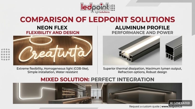
The operational synthesis: use neon flex when shape commands (signs, lettering, curves, exterior perimeters, continuous tube effect) and strip in profile when lumens and maintainability command. On mixed projects, which are the majority, the combination of the two technologies is often the technically and economically best solution.
17. Voltage drop, cable gauges and maximum lengths
Heat is not the only limit. On long runs, the dominant constraint becomes the voltage drop along the strip's PCB, which produces two undesirable effects: the end of the run illuminates less and, on white strips, tends to shift slightly in tone because the LEDs operate at reduced current.
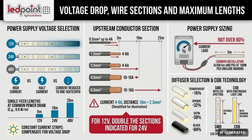
The phenomenon depends on the resistance of the copper traces, which is modest but not zero, and grows with current. This is why the supply voltage is the most powerful variable at your disposal: for the same power, going from 12V to 24V halves the current and reduces the voltage drop to a quarter; going from 12V to 48V reduces it to a sixteenth.
Table of recommended maximum lengths per single power supply
| Strip power | 12V, one-side feed | 12V, both-sides feed | 24V, one-side feed | 24V, both-sides feed | 48V, one-side feed |
|---|---|---|---|---|---|
| 4.8 W/m | 7 m | 14 m | 14 m | 28 m | 28 m |
| 9.6 W/m | 5 m | 10 m | 10 m | 20 m | 20 m |
| 14.4 W/m | 4 m | 8 m | 8 m | 16 m | 18 m |
| 19.2 W/m | 3 m | 6 m | 6 m | 12 m | 15 m |
| 24 W/m | 2.5 m | 5 m | 5 m | 10 m | 13 m |
| 30 W/m | 2 m | 4 m | 4 m | 8 m | 11 m |
The values are aimed at keeping the drop within 5-6% on the last section, a threshold below which the brightness difference is not perceptible to the naked eye. Strips with constant current control systems, available in the constant current LED strips section, behave differently: they maintain constant brightness along the entire run by internally compensating for the drop, and allow longer lengths for the same voltage.
Power supply conductor gauge
The previous table concerns the drop along the strip. Upstream is the drop on the cable carrying energy from the power supply to the connection point, and normal wiring practice applies here: keep the drop within 3% and size for the actual current.
| Absorbed current | Up to 3 m distance | Up to 6 m | Up to 10 m | Up to 15 m | Up to 25 m |
|---|---|---|---|---|---|
| up to 2 A | 0.50 mm² | 0.75 mm² | 1.0 mm² | 1.5 mm² | 2.5 mm² |
| 2-4 A | 0.75 mm² | 1.0 mm² | 1.5 mm² | 2.5 mm² | 4.0 mm² |
| 4-6 A | 1.0 mm² | 1.5 mm² | 2.5 mm² | 4.0 mm² | 6.0 mm² |
| 6-10 A | 1.5 mm² | 2.5 mm² | 4.0 mm² | 6.0 mm² | 10 mm² |
| 10-16 A | 2.5 mm² | 4.0 mm² | 6.0 mm² | 10 mm² | 16 mm² |
Indicative values for safety extra-low voltage circuits at 24V with the goal of contained drop. At 12V, double the indicated gauges: this is the most common mistake when reusing a 24V design.
Current absorbed per meter: the table to keep in the van
| Strip power | Current at 12V | Current at 24V | Current at 48V | Current for 5 m at 24V |
|---|---|---|---|---|
| 4.8 W/m | 0.40 A/m | 0.20 A/m | 0.10 A/m | 1.00 A |
| 9.6 W/m | 0.80 A/m | 0.40 A/m | 0.20 A/m | 2.00 A |
| 14.4 W/m | 1.20 A/m | 0.60 A/m | 0.30 A/m | 3.00 A |
| 19.2 W/m | 1.60 A/m | 0.80 A/m | 0.40 A/m | 4.00 A |
| 24 W/m | 2.00 A/m | 1.00 A/m | 0.50 A/m | 5.00 A |
| 30 W/m | 2.50 A/m | 1.25 A/m | 0.63 A/m | 6.25 A |
| 40 W/m | 3.33 A/m | 1.67 A/m | 0.83 A/m | 8.33 A |
18. Power supplies: sizing and derating
There is only one golden rule and it admits no exceptions: never load a power supply beyond 80% of its nominal power. A power supply working at 95-100% heats up, rapidly ages the electrolytic capacitors, and becomes the primary cause of failure of the entire system, often long before the strips it powers.
| Meters of strip | 4.8 W/m | 9.6 W/m | 14.4 W/m | 19.2 W/m | 24 W/m |
|---|---|---|---|---|---|
| 2 m | 15 W | 30 W | 40 W | 50 W | 60 W |
| 5 m | 30 W | 60 W | 100 W | 120 W | 150 W |
| 10 m | 60 W | 150 W | 200 W | 250 W | 320 W |
| 15 m | 100 W | 200 W | 320 W | 400 W | 2 x 250 W |
| 20 m | 120 W | 250 W | 400 W | 2 x 250 W | 2 x 320 W |
| 30 m | 200 W | 400 W | 2 x 300 W | 2 x 400 W | 3 x 320 W |
The values already include the 20-25% margin. For precise selection, the catalog offers 24V power supplies, 12V power supplies and 48V power supplies, as well as anti-flicker drivers for 230V strips.
Where to place the power supply
| Placement | Admissibility | Precautions |
|---|---|---|
| Electrical panel or ventilated technical compartment | Optimal | Verify the internal temperature of the panel |
| False ceiling with inspection hatch | Good | Ensure accessibility for maintenance |
| Inside the cabinet together with the strips | Acceptable with caution | Distance from hot aluminum, ensure air |
| Plastered false ceiling without access | To be avoided | Failure = demolition |
| In contact with thermal insulation | Forbidden | Risk of overheating and fire |
| Unprotected outdoors | Only with adequate IP | Verify IP rating and UV protection |
The fourth row describes a mistake that is paid for dearly. The power supply is the component with the shortest useful life in the entire chain: while a quality strip easily exceeds 40,000 hours, a power supply typically has a declared life on the order of 30,000-50,000 hours, and much less in unfavorable thermal conditions. Making it inaccessible means condemning the system.
19. Diffusers: how much flux you actually lose
The diffuser is the element that determines the perceived quality of the light. It is also the element that subtracts flux, and to a far from negligible extent. The following data are those detected on the photometric tests published for the PR-SL08-03 profile and represent the order of magnitude to be expected on profiles of comparable geometry.
| Diffuser type | Flux loss | Light uniformity | LED point visibility | Recommended application |
|---|---|---|---|---|
| Transparent | approx. −16% | Low | Points clearly visible | When maximum output is needed and the source is not in view |
| 60° lens transparent | approx. −16% | Medium | Points visible | Controlled beam, wall washing |
| Semi-opaque | approx. −20% | Good | Points attenuated | The most balanced compromise |
| Opaque | approx. −32% | Excellent | Points not visible with adequate density | Environments where the profile is in the field of view |
| Satin | approx. −39% | Excellent | Points not visible | Maximum softness, continuous effect |
| Black | approx. −84% | — | Source invisible when off | Scenographic effects, profile invisible when off |
The black diffuser data, with a loss on the order of 84%, is what surprises most people who encounter it for the first time. It is not a defect: it is its function. The black diffuser serves to make the profile invisible when turned off, and it is a precise scenographic choice. But it must be designed accordingly: if you need 1,000 lm/m output with a black diffuser, you must start with a strip capable of delivering over 6,000, with all the thermal consequences. In practice, the black diffuser is used with very low powers and only for point effects.
The LED-diffuser distance rule
There is a second criterion governing the choice, independent of flux loss: dotting, or the "pearl necklace" effect visible when individual LEDs are distinguished through the diffuser. It depends on the ratio between the LED pitch and the distance between the PCB and the diffuser surface.
| Strip density | Pitch between LEDs | Minimum distance from opaque diffuser | Minimum distance from semi-opaque diffuser | Recommended profiles |
|---|---|---|---|---|
| 30 leds/m | 33 mm | 20 mm | 30 mm | Tall T4-T5, or COB as an alternative |
| 60 leds/m | 16.7 mm | 12 mm | 18 mm | PR-SL05-03, PR-SL06-05, PR-RE13-23 |
| 120 leds/m | 8.3 mm | 7 mm | 10 mm | PR-SL16-16, PR-SL14-16, PR-RE12-16 |
| 240 leds/m | 4.2 mm | 4 mm | 6 mm | Virtually any profile |
| COB (384+ leds/m) | Continuous | 1 mm | 1 mm | Any profile, even the lowest |
Here is the real argument in favor of COB technology, which is often told poorly. The advantage of COB is not just aesthetic: it is design-oriented. By eliminating the distance constraint from the diffuser, COB allows you to use very low profiles even with an opaque diffuser, obtaining a perfectly continuous line of light in 8 mm of total height — something impossible with a 60 leds/m SMD strip.
20. The twelve mistakes we see most often on site
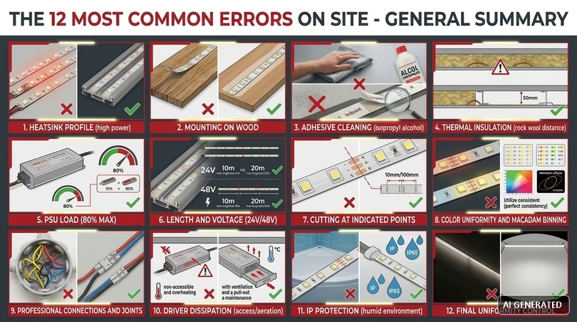
| # | Mistake | Consequence | How to avoid it |
|---|---|---|---|
| 1 | High power strip in T1 or T2 profile | Luminous depreciation within 12-24 months | Consult the tables in chapters 5-12 |
| 2 | No profile, strip glued to wood | Immediate overheating | The profile is not optional above 4.8 W/m |
| 3 | Adhesive applied to dusty surface | Partial thermal contact, detachment | Degrease with isopropyl alcohol before installation |
| 4 | Insulation in contact with the profile | Cancellation of dissipation | Set back rock wool by at least 30 mm |
| 5 | Power supply loaded to 100% | Premature power supply failure | Size to 80% maximum |
| 6 | 12V run too long from one side | Non-uniformity and chromatic shift | Switch to 24V/48V or feed from the center |
| 7 | IP65 jacketed strip in narrow IP20 profile | The strip doesn't fit or is forced | Use dedicated profiles for silicone |
| 8 | Strip cut outside designated points | Non-functioning segment | Cut only on the indicated marks |
| 9 | Clip connectors in humid environment | Trace corrosion, progressive shutdowns | Solder and seal |
| 10 | Mixing different batches on the same line | Visible chromatic differences | Order strips of the same batch and binning |
| 11 | Inaccessible power supply after finishing | Maintenance impossible without demolition | Always provide a hatch or technical compartment |
| 12 | Cold testing after a few minutes | Thermal problems do not emerge | Test after at least 2 hours at regime |
Mistake number 10 deserves a note, because it is insidious and has nothing to do with thermals. Two reels of the same strip, of the same code, but from different production batches, can present a perceptible color temperature difference when placed side by side on the same continuous line. The parameter governing this uniformity is called binning and is expressed in MacAdam ellipses: a product declared "3-step" guarantees that chromatic variations remain within an interval imperceptible to the eye in most conditions. On long and visible installations, always order the complete footage in a single solution and verify that the product declares the binning.
21. Operational selection and installation checklist
This is the section to print and keep in the van. Sixteen checks, in chronological order, from site survey to testing.
| Phase | # | Check | Done |
|---|---|---|---|
| Site survey | 1 | Measure the available space for the profile (width, height, depth) | ☐ |
| 2 | Detect the maximum foreseeable ambient temperature | ☐ | |
| 3 | Verify the presence of an air chamber behind the installation | ☐ | |
| 4 | Identify the position and accessibility of the power supply | ☐ | |
| Design | 5 | Define the target lux on the useful plane | ☐ |
| 6 | Convert to necessary lumens/meter (chapter 15) | ☐ | |
| 7 | Choose the strip efficiency and derive the W/m (chapter 14) | ☐ | |
| 8 | Apply the correction coefficients (chapter 13) | ☐ | |
| 9 | Verify the "Installable PCBs" field on the profile datasheet | ☐ | |
| Order | 10 | Order profile, diffuser, end caps, and clips together | ☐ |
| 11 | Order the complete footage in a single batch | ☐ | |
| 12 | Size the power supply to 80% of the load | ☐ | |
| Installation and testing | 13 | Degrease the seat before applying the strip | ☐ |
| 14 | Cut only on marked points and solder critical joints | ☐ | |
| 15 | Verify polarity before final closure | ☐ | |
| 16 | Thermal testing after 2 hours of continuous operation | ☐ |
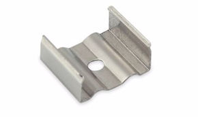
To complete the bill of materials, you also need the accessories that are often forgotten and that block the site: profile end caps, mounting clips, diffusers and LED strip connectors. For repetitive installations, there are profile and accessory kits, which bring everything together in a single reference.
22. Six practical cases solved with the tables
Case 1 - Perimeter drywall cove in a 30 m² living room
| Element | Data |
|---|---|
| Client request | Indirect ambient light, 22 meters of perimeter |
| Target lux | 100-150 lux of indirect illuminance |
| Required lumens/m | approx. 800 |
| Chosen strip | COB 24V at approx. 140 lm/W |
| Resulting W/m | 5.7 W/m → choose the commercial cut of 7 W/m |
| Profile | PR-DW16-03 for coves, class T3 |
| Thermal verification | 15.5 × 0.95 (opaque) × 0.85 (ventilated recess) = 12.5 W/m > 7 W/m — amply verified |
| Power supply | 22 m x 7 W = 154 W → two 100 W power supplies, fed from both sides |
Case 2 - Kitchen under-cabinet, 4.2 meters
| Element | Data |
|---|---|
| Request | 500 lux on the work surface, no glare |
| Required lumens/m | approx. 1,500 |
| Chosen strip | 2835 240 leds/m, 14.4 W/m, approx. 155 lm/W, 3000K CRI 80+ |
| Actual lumens | approx. 2,000 lm/m, reduced to approx. 1,600 with opaque diffuser |
| Profile | PR-AN02-08 16 mm angular, class T2 |
| Thermal verification | 14.4 × 0.95 × 0.70 (under closed cabinet) = 9.6 W/m < 14.4 W/m — not verified |
| Correction | Switch to PR-AN07-03 18x18mm or reduce to 9.6 W/m with a 180 lm/W strip |
| Final choice | PR-AN01-03 19x19mm hollow angular, class T3: 19.2 × 0.95 × 0.70 = 12.8 W/m — it remains prudent to reduce to 12 W/m |
This case is the most instructive of all, because it is the situation where most installations go wrong. The 16 mm angular profile with a 14.4 W/m strip under a closed cabinet is a combination seen daily and is out of specification. The solution costs almost nothing more: just go up one profile size, or use a more efficient strip.
Case 3 - Suspended line in open space office, 24 meters
| Element | Data |
|---|---|
| Request | 500 lux on the work surface according to UNI EN 12464-1 |
| Required lumens/m | approx. 2,800 with mixed direct/indirect emission |
| Chosen strip | High efficiency 160 lm/W |
| Resulting W/m | 17.5 W/m |
| Profile | PR-CL01-06 36x75mm, class T5 |
| Thermal verification | 45 × 0.97 (semi-opaque) × 1.10 (suspended) = 48 W/m — wide margin |
| Real constraint | Voltage drop: at 24V the maximum run is 8 m per side |
| Solution | Three independent power supplies, or switch to 48V with two 12 m branches |
Case 4 - Facade perimeter in neon flex, 40 meters
| Element | Data |
|---|---|
| Request | Continuous white line on cornice, visible from the street |
| Product | Neon flex 12x12 mm, IP67, 10 W/m, 24V |
| Mounting | NEO-1212-ACH aluminum bar on straight runs, NEO-1212-ACF on curved corners |
| Thermal verification | 10 W/m within the 14 W/m recommended for the section — verified |
| Power supply | 400 W total → four 150 W IP67 power supplies in distributed sealed enclosures |
| Runs | Maximum 10 m per 24V supply, therefore eight 5 m branches |
| Attention | Respect the minimum bending radius of 6-10 cm on corners |
Case 5 - Shower niche clad in porcelain stoneware
| Element | Data |
|---|---|
| Request | Accent light in niche, humid environment, zone 2 |
| Profile | PR-TI03-10 for 11 mm ceramic cladding |
| Strip | IP65 at 24V, 9.6 W/m, 4000K |
| Thermal verification | 9.6 × 0.90 (silicone) × 0.65 (embedded in adhesive) = 5.6 W/m — not verified |
| Correction | Reduce to 4.8 W/m with high efficiency strip (approx. 700 lm/m, adequate for an accent) |
| Power supply | SELV 24V with power supply outside the bathroom volume |
| System note | Verify volumes according to CEI 64-8 section 701 and make soldered and sealed joints |
Case 6 - High brightness retail showcase
| Element | Data |
|---|---|
| Request | 1,500 lux on the displayed product, CRI ≥ 95 |
| Required lumens/m | approx. 3,500 |
| Thermal constraint | Closed showcase, sun exposure, internal environment up to 40 °C |
| Chosen strip | High efficiency CRI 95, 140 lm/W → 25 W/m |
| Profile | PR-SL18-25 35x35mm, class T5 |
| Thermal verification | 40 × 0.97 × 0.70 (closed showcase) × 0.75 (40 °C) = 20.4 W/m < 25 W/m — not verified |
| Correction | Forced ventilation of the showcase, or two 12.5 W/m lines on two separate profiles |
| Final choice | Double line on PR-SL01-01 21x25mm, with load distribution and better uniformity |
Case 6 illustrates a design technique that solves many difficult situations: when the required power exceeds the capacity of a single profile, do not look for a larger profile — split the line. Two 12.5 W/m profiles dissipate better than one 25 W/m profile, often cost less than a higher class profile, and additionally produce more uniform and less directional lighting.
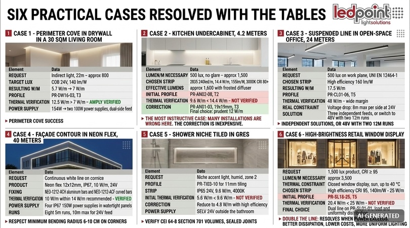
23. Useful regulatory references
| Standard or norm | Subject | Relevance for the installer |
|---|---|---|
| UNI EN 12464-1 | Lighting of indoor work places | Defines illuminance levels, uniformity, and glare limits (UGR) |
| UNI EN 12464-2 | Lighting of outdoor work places | Reference for outdoor areas, paths, and yards |
| CEI 64-8 | Low voltage electrical installations | Section 701 for bathrooms, SELV criteria for extra-low voltage |
| IEC/EN 60598 | Luminaires | General safety requirements for luminaires |
| IEC/EN 62031 | LED modules for general lighting | Safety requirements for modules, including strips |
| EN 62471 | Photobiological safety | Optical radiation hazard classification, relevant for high luminances |
| IES LM-80 | Measuring LED lumen maintenance | Experimental basis for life declarations |
| IES TM-21 | Projecting long term lumen maintenance | Method for extrapolating LM-80 data (L70, L80, L90) |
| EN 60529 | Degrees of protection provided by enclosures (IP code) | Definition of IP20, IP65, IP67, IP68 |
| EU Regulation 2019/2020 | Ecodesign for light sources | Energy class and efficiency requirements declared on the label |
Regulatory references should always be consulted in their current version: technical standards are periodically updated and some, like UNI EN 12464-1, have undergone substantial revisions in recent years with the introduction of concepts such as modulable illuminance and requirements related to the non-visual effects of light.
24. Frequently asked questions
Can I install an LED strip without an aluminum profile?Only with very low powers, up to about 4.8 W/m, and on surfaces that are not insulating. Above this threshold, the aluminum profile is necessary to dissipate heat: without dissipation, the junction temperature rises, luminous flux decays, and useful life is drastically reduced. On wood, drywall, or plastic, the profile is indispensable at any significant power. |
How do I know if a strip fits into a specific profile?Compare the strip's PCB width with the "Installable PCBs" field indicated in the profile's technical datasheet. For example, the 17x8mm PR-SL08-03 profile declares installable PCBs up to 12 mm, so it accepts 8, 10, and 12 mm strips. Remember that strips with IP65 silicone jacket are 1.5-3 mm wider than the bare PCB. |
What is the maximum LED strip power for a standard 17x8mm profile?In surface installation with a diffuser and 25 °C ambient temperature, the prudent limit is 14.4 W/m. If the same profile is recessed or installed in a closed cabinet, the limit drops to about 11.5 and 9.6 W/m, respectively. For higher powers, you must move to a larger cross-section profile. |
Why did my LED strip change color after a year?In almost all cases, the cause is overheating. Excessive heat degrades the LED conversion phosphors and produces a chromatic shift, typically towards yellow or green, often non-uniform along the run. It is the classic symptom of a strip oversized relative to the profile's dissipating capacity or installed without a profile. |
Are 12V or 24V LED strips better?For the same power, 24V circulates half the current compared to 12V, reducing the voltage drop to a quarter and allowing longer runs with smaller cable gauges. For fixed installations, 24V is almost always the best choice. 48V is ideal for very long lines, while 12V remains useful in mobile applications or where that voltage is already available. |
What is the difference between a COB and an SMD strip?The COB strip features a continuous luminous line without distinguishable points, because the chips are covered by a uniform phosphor layer. The SMD mounts discrete LEDs at a defined pitch, visible through transparent diffusers. COB allows the use of very low profiles without a dotting effect and is preferable wherever the profile is in the field of view. |
How much flux do I lose by mounting an opaque diffuser?On standard geometry profiles, the loss with an opaque diffuser is on the order of 32%, while satin reaches about 39% and transparent stays around 16%. The black diffuser, used to make the profile invisible when off, subtracts about 84% of the flux. These must be considered when sizing lumens. |
Can I mount two strips side by side in the same profile?Only if the profile has a sufficiently wide seat and belongs to a thermal class adequate for the sum of the two powers. Two 14.4 W/m strips mean 28.8 W/m of thermal load in the same body: a T4 or T5 class profile is required. Always verify both the total PCB width and the total power. |
Does neon flex need a profile to dissipate heat?The neon flex silicone body acts as a diffuser and protection; the dedicated aluminum bars serve primarily for mounting and alignment, with a secondary contribution to dissipation. For this reason, neon flexes have structurally contained powers, generally between 6 and 16 W/m depending on the section. |
Which profile do I choose for the bathroom or outdoors?You need waterproof profiles with gaskets and a sealed diffuser, paired with strips with an adequate IP rating. Consider that sealing reduces the dissipating capacity by 30-50%: for the same cross-section, an IP65 profile supports fewer watts than an IP20 one. Always also verify the clearance volumes required by CEI 64-8 for bathrooms. |
How do I check on site if the strip is overheating?Run the system for at least two continuous hours, then place the back of your hand on the profile. If you cannot keep it pressed for more than a few seconds, you are likely over 55-60 °C surface temperature, a condition indicating an out-of-specification match. A more precise verification is done with an infrared thermometer or thermal camera. |
How much should the power supply be oversized?Do not load it beyond 80% of its nominal power. For 5 meters of 14.4 W/m strip, i.e., 72 W, you need a power supply of at least 100 W. The margin protects the capacitors from accelerated aging and significantly reduces the risk of failure, which in the LED chain is almost always the weakest link. |
Can I cut the aluminum profile to size?Yes, with a disc cutter for aluminum and a fine-toothed blade. After cutting, carefully deburr the internal edges, otherwise the burr can cut the adhesive or the strip traces during insertion. Remember that profiles and diffusers have a dimensional tolerance of about ±2 mm on length. |
Are there profiles already complete with a strip?Yes, there are preassembled LED bars in which the profile, strip, diffuser, and wiring are already paired and verified in the factory. They are the fastest solution with the lowest risk of matching error, particularly suitable for sites with repetitive footage or when installation is entrusted to different crews. |
The profile is chosen before the strip, not after
If we were to reach a conclusion, it would be this: the matching between profile and LED strip is not a finishing detail, it is a design choice that must be made at the beginning, not at the end. In daily practice, almost the opposite happens. The strip is chosen by looking at lumens and price, then the profile that fits inside and into the already-made cove is sought. This is exactly the wrong order, and it is the reason why a significant portion of the problems that reach support (luminous depreciation, chromatic shift, dead segments, adhesive detachment) does not arise from a product defect but from an insufficient thermal coupling decided upstream.
The method we have proposed reverses the sequence and rests on five steps you now know: start from the required lux, convert them to lumens per meter, divide by the strip's efficiency to get the actual watts, verify the PCB width on the field declared in the profile datasheet, and finally check the thermal class by applying the correction coefficients of your actual installation. It is five minutes of work during the quoting phase. It is worth days of saved return trips to the site.
Three concepts, more than all others, concretely change the way of working. The first is that luminous efficiency is the most powerful lever you have: every lumen per watt gained is heat you don't have to dissipate, and a 160 lm/W strip often allows you to drop two profile classes, with a lower system cost and simpler installation. The second is that the same strip in the same profile behaves completely differently depending on how it is installed: surface mounted, recessed with an air chamber, plastered, or inside a closed cabinet are four scenarios with four different limits, and reading the right column of the table is all it takes not to make a mistake. The third is that when the required power exceeds the capacity of a profile, splitting the line is almost always better than enlarging the profile: two half-power lines dissipate better, illuminate more uniformly, and often cost less than a single higher-class solution.
One last piece of advice remains, the simplest and the most ignored: test hot. Two hours of continuous operation and the back of your hand on the profile tell you, without instrumentation and without calculations, whether the job will last ten years or two. It is the final check that closes the circle of everything you have read here.
And if, after all the tables, doubt remains, the Ledpoint technical office will evaluate the specific case with you before ordering. A verified match during the quoting phase costs a phone call; verified during a failure, it costs a construction site.
This article was developed with the support of artificial intelligence and subsequently reviewed, corrected, and validated by the Ledpoint.it technical team, which guarantees its reliability and compliance with official sources. The maximum power values per thermal class are prudent sizing criteria: always verify the specifications declared in the technical datasheet of the individual product.