







UV LEDs and molds: spectra, doses, and real-world applications for the treatment and control of fungal contamination.
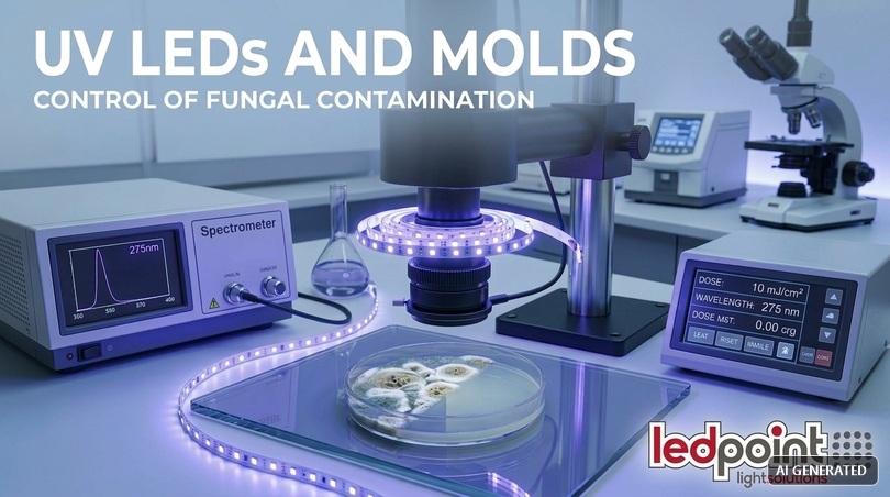
Ultraviolet radiation acts on molds by inactivating the DNA of fungal spores: UV-C (200–280 nm) is the true germicidal band, UV-B (280–315 nm) has intermediate biological action, UV-A (315–400 nm) does not sterilize but makes colonies visible through fluorescence and drives oxidative photocatalysis on titanium dioxide. The result depends on the dose in mJ/cm², not on the declared power.
This technical guide was born from a question we receive with increasing frequency in our technical office in Faenza: “Can I use UV LEDs to eliminate mold?”. The honest answer is: yes, but only if you understand which spectrum you are using, what dose you are delivering, and what problem you are actually solving. In the following pages you will find the physics, the microbiology, the numbers, the regulations, eleven documented sector case studies, three projects that can be built with Ledpoint catalog products, and a section on mistakes to avoid that is, by itself, worth the reading time. No miracle promises: only lighting engineering applied to environmental microbiology.
In this article...
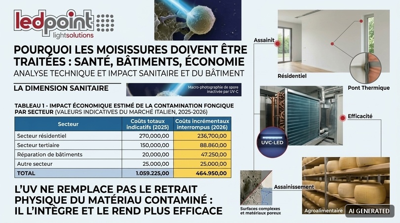
1. Why molds must be treated: health, buildings, economics
Before talking about nanometers and millijoules, it is worth establishing the scope of the problem, because mold is not an aesthetic defect: it is a living organism that colonizes building materials, food, textiles, and technical surfaces, and releases spores, hyphal fragments, microbial volatile organic compounds, and, in some species, mycotoxins into the air. Treating mold means intervening simultaneously on a health problem, a material conservation problem, and an economic problem, and any UV lighting project that ignores one of these three dimensions is badly set up from the start.
The health dimension
The epidemiological evidence on exposure to moisture and molds in enclosed environments is among the most solid in environmental medicine. The World Health Organization guidelines on indoor air quality dedicated to moisture and mold have consolidated a clear position: exposure to damp and moldy environments is associated with a significant increase in respiratory symptoms, asthma, upper airway infections, cough, wheezing, and dyspnea. Available meta-analyses indicate increases on the order of 30–50% in the risk of respiratory outcomes in exposed subjects compared with unexposed subjects, with a more marked effect in children, the elderly, and subjects who are already asthmatic or immunocompromised.
The mechanism is not unique. Fungal spores, with typical diameters between 2 and 10 micrometers, penetrate deeply into the respiratory tract and act as allergens. Submicronic hyphal fragments, more numerous than the spores themselves, add an allergenic load that is difficult to filter. Some genera produce mycotoxins: aflatoxins from Aspergillus flavus, ochratoxins from Aspergillus ochraceus and Penicillium verrucosum, trichothecenes from Stachybotrys chartarum. Finally, microbial volatile organic compounds (MVOCs) (geosmin, 1-octen-3-ol, 2-methylisoborneol) are responsible for the characteristic cellar odor and can cause mucous membrane irritation even at very low concentrations.
One point that must be stated clearly from the beginning: ultraviolet radiation inactivates the replicative capacity of spores, but does not make them disappear. An inactivated spore remains an allergenic protein body. Mycotoxins are chemically stable molecules that UV degrades only partially and with very high doses. This means that UV never replaces the physical removal of contaminated material and the remediation of the moisture cause: it integrates it, makes it more effective, and maintains its results over time.
The building and conservation dimension
On the construction side, fungal colonization is both a symptom and an agent of degradation. Filamentous fungi degrade cellulose and hemicelluloses, thus attacking wallpaper, drywall, wood, textiles, paintings, books, and archives. They produce organic acids (oxalic, citric, gluconic) that attack binders, mortars, and stone surfaces. Hyphae penetrate the micropores of materials to a depth that in drywall can exceed 5 millimeters, making any purely surface treatment, including UV, completely ineffective if not preceded by mechanical removal.
In the cultural heritage sector the problem is amplified: museum storage, state archives, historical libraries, and restoration warehouses coexist with enormous volumes of hygroscopic organic material, often in historic buildings without active climate control. In these contexts, fungal contamination is the leading cause of irreversible loss of documentary heritage, and paradoxically this is precisely where UV must be used with maximum caution, because the same radiation that inactivates spores degrades pigments, inks, and binders.
The economic dimension
Eurostat data based on the EU-SILC survey have indicated for years that a share between 14% and 16% of the European Union population lives in dwellings with roof leaks, dampness in walls, floors, or foundations, or with rot in window frames. Italy consistently sits at values comparable to the European average. Translated into absolute numbers, this means tens of millions of housing units with the triggering conditions for fungal proliferation.
| Sector | Main cost item | Order of magnitude | Typical recurrence |
|---|---|---|---|
| Residential | Remediation of moldy wall from condensation (10 m²) | 600–2,500 € | Every 2-4 years if the cause is not removed |
| Residential | Intervention on thermal bridge with internal insulation | 80–160 €/m² | One-time |
| Commercial HVAC | Chemical cleaning of AHU cooling coil | 400–1,200 € per unit | Annual or semiannual |
| Commercial HVAC | Extra energy consumption from biological fouling | +10÷25% on cooling capacity | Continuous |
| Agri-food | Rejection due to fungal contamination during curing | 1–5% of batch | Per production cycle |
| Oenology | Cleaning of barrels and aging rooms | 150–600 € per barrique | Per cycle |
| Greenhouses and nurseries | Loss from Botrytis cinerea on protected crops | 5–20% of production | Seasonal |
| Archives and museums | Pest control and restoration of contaminated documents | 20–200 € per documentary unit | Extraordinary event |
| Marine | Cleaning of interiors, upholstery, and bilges | 800–4,000 € per unit | After winter storage |
Reading this table suggests a strategic consideration: UV makes economic sense especially where the problem is recurrent and the cost of each remediation cycle is high. In a single home wall with mold from a thermal bridge, the solution is to insulate and ventilate, not install LEDs. In an AHU cooling coil that requires chemical cleaning every year and loses efficiency, an in-line UVGI system pays for itself in 12-24 months. It is the difference between using the right technology and using fashionable technology.
2. How a mold works: spores, hyphae, biofilm, and available water
No UV project works if the target is not known. Molds are multicellular filamentous fungi whose life cycle is divided into three phases with radically different resistance to radiation, and it is this difference (not the power of the source) that determines the success or failure of a treatment. Designing a UV system thinking that all fungal forms behave the same way is the most widespread conceptual error in the sector.
The three phases of the cycle and their sensitivity
The spore is the form of resistance and dissemination. It is metabolically quiescent, protected by a thick cell wall and, in pigmented species, by melanin. Melanin is a broad-spectrum absorber that effectively shields ultraviolet radiation: this is why Aspergillus niger and Cladosporium (black molds) require UV-C doses even ten or twenty times higher than those needed for a vegetative bacterium such as Escherichia coli.
The hypha is the vegetative filament that grows in the substrate. It is metabolically active, lacks melanin in the early stages, and is therefore much more sensitive to radiation. The problem is that the hypha grows inside the material: in drywall, wood, plaster. UV-C radiation has practically zero penetration power (it is absorbed in the first micrometers of any opaque material), so internal hyphae are untouchable.
The mature mycelium with fruiting bodies is the visible colony. The exposed surface is inactivated, but the underlying layer is shielded by the upper layer. This is the technical reason why UV does not clean an existing mold stain: it makes it non-viable on the surface and blocks sporulation, but the stain remains and the colonized substrate must still be removed.
Available water: the parameter that affects everything
The physical parameter governing fungal growth is not the relative humidity of the air, but the water activity (aw) of the substrate, that is, the ratio between the vapor pressure of water in the material and that of pure water at the same temperature. The value, between 0 and 1, determines which species can establish themselves.
| Genus | Minimum aw | Corresponding equilibrium RH | Ecological category | Typical habitat |
|---|---|---|---|---|
| Aspergillus restrictus | 0.71 | ~71% | Extreme xerophile | Dust, archives, textiles |
| Aspergillus versicolor | 0.78 | ~78% | Xerophile | Cold walls, wallpaper |
| Penicillium chrysogenum | 0.80 | ~80% | Xerophile | Cellars, food, leather |
| Aspergillus niger | 0.82 | ~82% | Moderately xerophile | Bathrooms, sanitary silicone |
| Cladosporium sphaerospermum | 0.85 | ~85% | Mesophile | Window frames, HVAC coils |
| Alternaria alternata | 0.88 | ~88% | Mesophile | Condensation, window sills |
| Botrytis cinerea | 0.93 | ~93% | Hydrophile | Greenhouses, grapes, post-harvest |
| Stachybotrys chartarum | 0.94 | ~94% | Hydrophile | Wet drywall, infiltration |
| Fusarium spp. | 0.90 | ~90% | Hydrophile | Agricultural substrates, hydroponics |
If you keep the substrate stably below aw 0.70 (i.e., in equilibrium with air at 70% RH at surface temperature), no mold grows, without any treatment. This leads to a rule we always repeat to designers: the first anti-mold system is hygrothermal control; UV is the second, and it serves to manage what hygrothermal control cannot eliminate, typically the airborne microbial load, intrinsically wet surfaces such as cooling coils, and environments where humidity is a process requirement (curing, aging, greenhouses).
The temperature factor and the surface factor
A third often overlooked element is surface temperature. The phenomenon of condensation mold is triggered when the temperature of a surface falls below the dew point of the ambient air. In an apartment at 20 °C and 60% RH, the dew point is about 12 °C: any surface colder than 12 °C condenses. In thermal bridges (corners between external walls, window reveals, uninsulated roof slabs) this condition is structural.
Finally, surface roughness: a smooth, non-porous surface such as stainless steel, glass, or anodized aluminum is much easier to treat with UV because the target is geometrically exposed. A porous surface (civil plaster, raw wood, drywall) creates micro-shadows where radiation does not reach. In UV design, geometry always wins over power, and this concept will return repeatedly throughout the article.
3. The ultraviolet spectrum: UV-A, UV-B, UV-C, Far-UVC, and UV-V
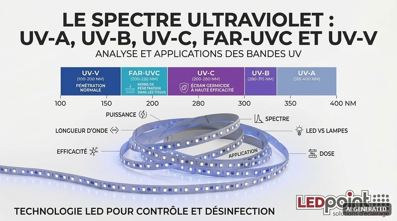
Ultraviolet radiation occupies the portion of the electromagnetic spectrum between 100 and 400 nanometers, immediately below visible light, which conventionally begins at 380–400 nm. It is not a homogeneous band: within it, physical properties and biological effects change radically every few tens of nanometers. Talking generically about a “UV lamp” without specifying the peak wavelength is technically meaningless, and it is precisely on this ambiguity that many low-value consumer products thrive.
| Band | Range | Photon energy | Effect on fungi | Penetration into human tissues | Typical applications |
|---|---|---|---|---|---|
| UV-A | 315-400 nm | 3.10-3.94 eV | No relevant direct germicidal action; indirect effect via ROS and photocatalysis | High: reaches the dermis | Fluorescence and diagnosis, TiO₂ photocatalysis, resin polymerization, insect traps, document authentication, cultivation |
| UV-B | 280-315 nm | 3.94-4.43 eV | Intermediate biological action, induces defense responses in plants | Medium: epidermis, erythema | Dermatological phototherapy, vitamin D synthesis, modulation of secondary metabolites in agriculture |
| UV-C | 200-280 nm | 4.43-6.20 eV | Maximum germicidal action, peak efficacy 260–265 nm | Low: stratum corneum and cornea, but harmful | Air/water/surface disinfection (UVGI), HVAC treatment, sterilization |
| Far-UVC | 200-230 nm (peak 222 nm) | 5.39–6.20 eV | Germicidal, effective on spores and viruses | Very low: absorbed by the stratum corneum | Disinfection in occupied environments (emerging technology) |
| UV-V (Vacuum UV) | 100-200 nm | >6.20 eV | Germicidal but absorbed by air | Does not reach skin in air | Ozone generation (185 nm), industrial processes under vacuum |
Why the germicidal peak is at 265 nm
The germicidal efficacy of radiation is not uniformly distributed within the UV-C band: it follows an action curve that replicates the absorption spectrum of nucleic acids. DNA has an absorption maximum around 260–265 nm, due to the aromatic structure of nitrogenous bases. This defines the so-called relative germicidal efficacy curve, normalized to 1.0 at the peak.
| Wavelength | Relative efficacy | Typical source | Technical notes |
|---|---|---|---|
| 222 nm | ≈ 0.55–0.75 | KrCl excimer lamp | Low tissue penetration, high safety |
| 254 nm | ≈ 0.85 | Low-pressure mercury vapor lamp | Historic industrial standard, contains mercury |
| 265 nm | 1.00 | AlGaN UV-C LED | Theoretical peak efficacy, electrical efficiency still low |
| 275 nm | ≈ 0.75–0.85 | Most common commercial UV-C LED | Best current output/cost compromise |
| 285 nm | ≈ 0.50–0.60 | Boundary UV-B/UV-C LED | Efficacy declining rapidly |
| 310 nm | ≈ 0.02–0.05 | UV-B LED | Practically non-germicidal |
| 365 nm | < 0.001 | UV-A LED | Negligible direct germicidal action |
| 395 nm | < 0.0005 | UV-A LED / violet chip | Only indirect photodynamic effect |
This fact deserves to be fully absorbed, because it has enormous commercial consequences. A 365 nm or 395 nm LED, however powerful, is not a germicidal source. If a product on the market claims sterilization with 395 nm LEDs, it is either exploiting a completely different mechanism (photocatalysis, for example) or simply making false claims. In the Ledpoint catalog this distinction is explicit: the UV LED strips in the Ultraviolet section are UV-A sources at 365 nm and 380 nm, designed for fluorescence, photocatalysis, process control, and technical applications, not for direct disinfection.
UV LEDs versus traditional lamps: a comparison without fan bias
The transition from mercury vapor discharge sources to solid-state UV diodes is still underway, with very different dynamics depending on the band. In UV-A, LED technology has already won: electro-optical efficiencies of 30–50%, useful life over 20,000 hours, instant start, dimmability, no mercury. In UV-C the situation is more nuanced: AlGaN LEDs at 275 nm have efficiencies typically between 2% and 6%, versus 30–35% for a low-pressure 254 nm lamp, and declared useful lives between 5,000 and 15,000 hours at L70.
| Parameter | UV-A LED 365–395 nm | UV-C LED 265–285 nm | Low-pressure Hg lamp 254 nm | KrCl excimer lamp 222 nm |
|---|---|---|---|---|
| Electro-optical efficiency (WPE) | 30–50% | 2–6% | 30–35% | 2–8% |
| Useful life (L70) | 20,000–50,000 h | 5,000–15,000 h | 8,000–16,000 h | 3,000–6,000 h |
| Time to reach full output | < 1 ms | < 1 ms | 1–5 minutes | < 1 s |
| Switching cycles | Unlimited | Unlimited | Drastically reduce life | Limited |
| Dimmability | Full (PWM/analog) | Full | Very limited | Partial |
| Mercury content | Absent | Absent | Present (RoHS, special disposal) | Absent |
| Low-temperature performance | Excellent | Excellent, better when cold | Degraded below 15 °C | Good |
| Cost per radiant mW | Low | High | Very low | Very high |
| Typical format | Strips, bars, modules, spotlights | Modules, spotlights, short bars | Linear tubes | Dedicated fixtures |
The design conclusion is simple. For large volumes and limited budgets in UV-C, low-pressure lamps remain technically and economically superior; for compact, integrated, frequently cycled, low-temperature, or moving applications, UV-C LEDs are already the right choice; for everything involving fluorescence, photocatalysis, process control, and architectural integration, UV-A LEDs are the only sensible choice. The 365 nm and 380 nm UV-A LED strips in the Ledpoint catalog belong to this latter family, and in the following chapters we will see exactly what functions they can perform in an overall anti-mold strategy.
4. Mechanism of action: pyrimidine dimers, dose, and inactivation curves
Once you understand which band does what, the question that determines the success of every project remains: “What exactly happens inside a spore hit by a UV-C photon, and how many photons are needed?” The answer to this question is the difference between a system that works and a system that consumes electricity without producing results. In the UV world there is no concept of “on, therefore effective”: there is only dose.
Photochemical damage to DNA
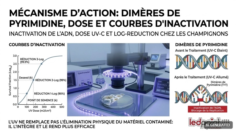
When a photon with energy between 4.4 and 6.2 eV (i.e., in the UV-C band) is absorbed by a pyrimidine base adjacent to another pyrimidine base on the same DNA strand, a [2+2] cycloaddition reaction is triggered that forms a covalent bond between the two bases. The result is a cyclobutane pyrimidine dimer (CPD), typically a thymine dimer, or a 6-4 pyrimidine-pyrimidone photoproduct.
This lesion distorts the double helix and physically blocks the progression of DNA polymerase and RNA polymerase. The cell does not die immediately: it loses the ability to replicate. In microbiological language, therefore, one speaks of inactivation and not killing, and the distinction is anything but academic, because it opens the chapter on photoreactivation.
Photoreactivation and dark repair: the invisible enemy
Many microorganisms, including fungi, have enzymatic DNA repair systems. The most relevant for UV design is photolyase, an enzyme that uses the energy of blue and UV-A light (typically 330–480 nm) to cleave the pyrimidine dimer and restore the original bases. The phenomenon is called photoreactivation.
There is also dark repair, mediated by the nucleotide excision system, slower but independent of light. The design implications are three, and they must be considered mandatorily:
- oversize the dose relative to the theoretical minimum value, with a typical factor of 1.5 to 3, to saturate the cell’s repair capacity;
- avoid exposing to intense visible light immediately after UV-C treatment, where possible, because blue light activates photolyase. In night cycles in cells and chambers this happens naturally;
- prefer continuous low-dose treatments over sporadic high-dose pulses, in contexts where possible: constant pressure prevents population recovery.
The dose formula: the heart of every calculation
The quantity that determines the biological effect is the UV dose, also called fluence, expressed in millijoules per square centimeter (mJ/cm²) or equivalently in microwatt-seconds per square centimeter. The fundamental relationship is disarmingly simple:
Dose (mJ/cm²) = Irradiance (mW/cm²) × Exposure time (s)
Where irradiance is the radiant power incident on the unit area of the target. From this formula derive the two available design levers: increase irradiance (more power, shorter distances, concentrating optics, reflective surfaces) or increase time. In the vast majority of civil and industrial applications, lengthening time is by far the cheapest and most effective strategy, because irradiance falls with the square of the distance while time grows linearly and costs only electricity.
The inverse-square law and its betrayal
For a point source, irradiance decays according to E = P / (4πd²), where P is radiant power and d is distance. Doubling the distance reduces irradiance to one quarter; tripling it, to one ninth. This is why a portable UV-C lamp that produces excellent results at 10 cm produces one hundredth of the irradiance at 1 meter and becomes practically useless in reasonable times.
Linear sources (and LED strips are linear) behave differently. Close to a linear source that is long relative to the distance, irradiance decays approximately linearly with distance (1/d) rather than quadratically, because each point on the target sees an increasing number of emitters as it moves away, until the finite length of the strip makes itself felt. This is a substantial and little-known advantage of strip configurations: they cover extended surfaces with much gentler irradiance gradients than point sources.
| Distance from target | Relative irradiance, point source | Relative irradiance, extended linear source | Time required for the same dose (linear) |
|---|---|---|---|
| 10 cm | 100% | 100% | 1× |
| 20 cm | 25% | 50% | 2× |
| 30 cm | 11% | 33% | 3× |
| 50 cm | 4% | 20% | 5× |
| 100 cm | 1% | 10% | 10× |
| 200 cm | 0.25% | 5% | 20× |
The inactivation curve and the concept of log-reduction
Microbial inactivation follows, to a first approximation, first-order kinetics described by the Chick-Watson law: N/N₀ = e−k·D, where N/N₀ is the surviving fraction, k the specific sensitivity constant of the microorganism, and D the dose. On a logarithmic scale the curve is a straight line.
In practice, the concept of logarithmic reduction is used: 1 log equals 90% inactivation, 2 log 99%, 3 log 99.9%, 4 log 99.99%. The jump from 3 to 4 log requires the same dose that was needed to go from 0 to 1 log, and this proportionality is what makes chasing extreme performance expensive.
| Log reduction | Inactivation % | Survivors out of 1,000,000 | Relative dose required | Typical context of adequacy |
|---|---|---|---|---|
| 1 log | 90% | 100,000 | 1× | Containment in residential environments |
| 2 log | 99% | 10,000 | 2× | HVAC, biofilm prevention |
| 3 log | 99.9% | 1,000 | 3× | Agri-food, packaging |
| 4 log | 99.99% | 100 | 4× | Cleanrooms, pharmaceutical |
| 5 log | 99.999% | 10 | 5× | Sterilization of devices |
| 6 log | 99.9999% | 1 | 6× | Aseptic processes |
One real complication must be added: fungal inactivation curves frequently show a tailing phenomenon, i.e., flattening at high doses due to resistant subpopulations, spore aggregation, and the shielding effect of dust particles. This is the technical reason why promising “total mold elimination” with a UV system is, literally, a physically unkeepable promise.
5. How much dose is really needed: table by fungal species
Now we come to the numbers that really matter for sizing a system. It must be premised that values reported in the literature vary by as much as an order of magnitude depending on substrate, physiological state of spores, relative humidity during exposure, presence of organic matter, and counting method. The data below should be used as a sizing basis with safety factors, never as a punctual guarantee.
| Microorganism | Dose for 1 log (90%) | Dose for 2 log (99%) | Dose for 3 log (99.9%) | Pigmentation | Relative difficulty |
|---|---|---|---|---|---|
| Escherichia coli (bacterial reference) | 3–7 mJ/cm² | 6–10 mJ/cm² | 9–15 mJ/cm² | Absent | Very low |
| Bacillus subtilis (bacterial spore) | 12–20 mJ/cm² | 25–40 mJ/cm² | 40–60 mJ/cm² | Absent | Medium |
| Penicillium chrysogenum | 25–60 mJ/cm² | 60–130 mJ/cm² | 110–200 mJ/cm² | Weak (blue-green) | Medium |
| Penicillium expansum | 30–70 mJ/cm² | 70–150 mJ/cm² | 130–230 mJ/cm² | Weak | Medium |
| Botrytis cinerea | 30–80 mJ/cm² | 80–160 mJ/cm² | 140–250 mJ/cm² | Weak-medium | Medium |
| Fusarium spp. | 40–90 mJ/cm² | 90–180 mJ/cm² | 160–300 mJ/cm² | Variable | Medium-high |
| Alternaria alternata | 60–120 mJ/cm² | 130–250 mJ/cm² | 220–400 mJ/cm² | Melanized | High |
| Cladosporium spp. | 60–130 mJ/cm² | 140–280 mJ/cm² | 240–450 mJ/cm² | Melanized | High |
| Stachybotrys chartarum | 70–150 mJ/cm² | 160–320 mJ/cm² | 280–500 mJ/cm² | Melanized | High |
| Aspergillus niger | 100–250 mJ/cm² | 250–500 mJ/cm² | 400–900 mJ/cm² | Strongly melanized | Very high |
Two immediate readings. First: fungal spores require doses ten to one hundred times higher than those for vegetative bacteria, and anyone sizing an anti-mold system using bacterial inactivation tables is off by orders of magnitude. Second: melanin is the true adversary, and the common “black mold” everyone wants to eliminate is precisely the most resistant category.
The relative humidity correction
A factor rarely cited in commercial manuals but well documented in the literature is the effect of relative humidity on UVGI efficacy in air. As relative humidity rises above 60–70%, germicidal efficacy drops significantly, for reasons including the formation of a hydrated film around spores, particle aggregation, and alteration of DNA conformation. The practical correction is shown below.
| Ambient relative humidity | Multiplying factor on dose | Design note |
|---|---|---|
| < 40% | 0.9× | Optimal condition, rare in mold-risk environments |
| 40–60% | 1.0× | Table reference |
| 60–75% | 1.3–1.6× | Typical of cellars, bathrooms, cells |
| 75–85% | 1.6–2.2× | Curing, greenhouses, process environments |
| > 85% | 2.2–3.0× | Critical condition: prioritize hygrothermal control |
This is why we repeat that UV is not an alternative to dehumidification: in the conditions where mold grows most readily, UV works worse. The correct sequence is always: control the water, remove contaminated material, then maintain the result with UV.
6. UV-A 365–380 nm: fluorescence diagnosis and contamination mapping
At this point someone may wonder why a professional lighting e-commerce site dedicates such an in-depth article to UV-C when its catalog contains UV-A strips. The answer is that UV-A performs, in mold management, two functions that UV-C cannot perform: making visible what cannot be seen and activating photocatalysis in the presence of people. The first is the topic of this chapter and is, by itself, worth the cost of the equipment.
The principle of induced fluorescence
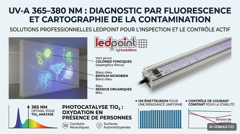
Many organic molecules, when struck by UV-A radiation, absorb energy and re-emit it at longer wavelengths, in the visible range. The phenomenon is called fluorescence, and in mycology it is extraordinarily useful because several fungal metabolites are powerful fluorophores.
| Target | Typical emission color | Responsible molecule or mechanism | Practical use |
|---|---|---|---|
| Fungal colonies on cereals (Aspergillus flavus) | Bright green-yellow | Oxidized kojic acid, correlated with aflatoxins | Pre-screening of stored batches |
| Penicillium colonies | Faint blue-green | Polyketide metabolites | Inspection of cellars and storage rooms |
| Microbial biofilm on surfaces | Diffuse white-blue | Proteins, NADH, flavins | Verification of system cleanliness |
| Organic and protein residues | Blue | Tryptophan, tyrosine | Surface sanitation control |
| Moisture and salt stains | Tone contrast | Different reflectance/emission | Mapping of capillary rise |
| Retouching and restorations on paintings | Dark against fluorescent background | Recent non-aged varnishes | Cultural heritage diagnostics |
| Circuit leaks (with tracer) | Intense green | Fluorescein tracers | Leak detection |
Why 365 nm and not 395 nm? It is the technical detail that separates a professional tool from a toy. 395 nm LEDs emit a significant share of radiation in the visible violet, producing a strong luminous veil that masks the weak fluorescent emission of the target. 365 nm LEDs have a much lower residual visible emission, providing markedly higher contrast and allowing detection of colonies and biofilms that would be invisible at 395 nm. For this reason, the UV LED strip 365–370 nm at 120 LEDs/m with current control is the ideal basis for building inspection devices: 120 emitters per meter ensure banding-free distribution, and the constant-current control system keeps irradiance stable along the entire length, something a voltage-controlled strip cannot do over long runs.
Building a professional LED Wood’s lamp
The classic Wood’s lamp is a UV-A source equipped with a filter that blocks visible light. Replicating its behavior with LEDs is simple, inexpensive, and produces superior results. The configuration we recommend in our technical office uses a 50–100 cm inspection bar, made with 365 nm UV strip mounted in an aluminum profile, powered at 24 V and dimmable to adapt intensity to the working distance.
The construction elements are as follows, all available in the catalog:
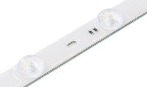
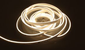
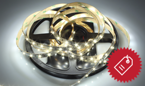
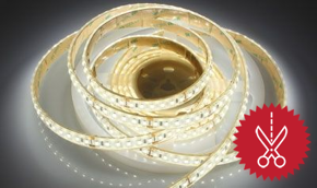
- Source: UV LED strip 365 nm 120 LEDs/m, 24 V, 14.4 W/m, cuttable every 5 cm, or the cheaper 60 LEDs/m version for less demanding uses.
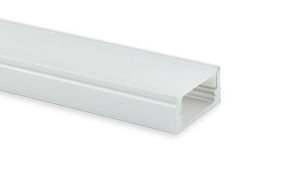
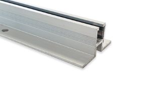
- Body and heat dissipation: an aluminum profile of suitable section; aluminum is essential because UV chips have performance strongly dependent on junction temperature.
- Optics: no opal diffuser. PMMA and polycarbonate diffusers absorb much of the UV-A and accelerate its yellowing; for UV applications, work with an open profile or covers in soda-lime glass or quartz.
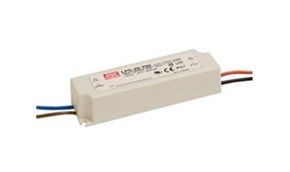
- Power supply: a 24 V power supply sized with at least 20% margin over nominal power.
- Control: a monochromatic dimmer to modulate irradiance according to inspection distance.
The result is a diagnostic tool that, during a technical survey, allows you to distinguish in a few minutes a moisture stain from active fungal colonization, to identify the real perimeter of contamination—almost always more extensive than what is visible to the naked eye—and to photographically document the before and after state. For a remediation company or a building diagnostics firm, it is the cheapest way to increase the perceived quality of the service.
Honest limits of fluorescence diagnosis
It must be stated just as clearly what UV-A fluorescence does not do. It does not identify the fungal species: for that, sampling and culture or molecular analysis are needed. It does not distinguish with certainty viable from inactivated material. It does not quantify microbial load. It also produces frequent false positives: fabric softeners, detergents with optical brighteners, some paints and resins, adhesive residues, and even certain papers fluoresce intensely. Fluorescence is a rapid screening and sampling-orientation tool, not an analytical method. Used that way, it is excellent; used as diagnostic proof, it is misleading.
7. TiO₂ + UV-A photocatalysis: oxidation that works in the presence of people
The second technical function of UV-A in controlling fungal contamination is conceptually more refined and commercially more interesting: photocatalytic oxidation, known in the literature as PCO (Photo-Catalytic Oxidation). Here UV-A does not act on the microorganism, but on a catalyst that in turn generates oxidizing chemical species.
The chemistry of the process
The standard catalyst is titanium dioxide (TiO₂) in anatase form, a semiconductor with a band gap of about 3.2 eV. A photon with energy above this threshold (corresponding to wavelengths below about 388 nm) promotes an electron from the valence band to the conduction band, generating an electron-hole pair.
The photogenerated holes oxidize adsorbed water, producing hydroxyl radicals (•OH), among the most powerful oxidants known, with an oxidation potential of 2.8 V. The electrons reduce molecular oxygen, generating superoxide anions (O₂•⁻). These reactive oxygen species non-selectively attack the cell membranes, proteins, and nucleic acids of microorganisms that come into contact with the catalytic surface, and progressively mineralize volatile organic compounds.
The 388 nm threshold explains why 365 nm and 380 nm LEDs are exactly the correct sources to drive a photocatalytic system, while 395 or 405 nm LEDs (although marketed as UV) largely fall below the necessary energy threshold and activate anatase TiO₂ much less efficiently.
| Peak wavelength | Photon energy | Exceeds band gap (3.2 eV)? | Relative activation efficiency | Application judgment |
|---|---|---|---|---|
| 365 nm | 3.40 eV | Yes, with margin | 100% (reference) | Optimal |
| 375 nm | 3.31 eV | Yes | ~90% | Very good |
| 380 nm | 3.26 eV | Yes, marginally | ~75% | Good, excellent cost/performance ratio |
| 390 nm | 3.18 eV | No (below threshold) | ~25% | Insufficient on pure anatase |
| 400–405 nm | 3.06–3.10 eV | No | < 10% | Requires doped TiO₂ (visible-light) |
It should be noted that there are TiO₂ formulations doped with nitrogen, carbon, or transition metals, designed to work with visible light. They are technologically interesting but typically less efficient and less stable than pure anatase activated in UV-A. For a professional system, the pair of anatase + 365 nm LED remains the combination with the best performance/reliability ratio.
Where photocatalysis makes sense and where it does not
PCO is a maintenance technology, not a remediation one. Kinetics are slow compared with direct UV-C, efficacy depends critically on contact time between air and the catalytic surface, and the catalytic surface progressively poisons due to accumulation of inorganic compounds and particulate matter. Its decisive advantage is only one, but enormous: UV-A at 365–380 nm, correctly shielded and confined within the device, allows continuous operation even in the presence of people, which UV-C does not allow in an open configuration.
The contexts in which photocatalysis produces measurable results are:
- Air ducts: where air is forced through an irradiated catalytic element, with contact times controlled by flow velocity.
- Self-cleaning vertical surfaces: treated with photocatalytic coatings and irradiated continuously and at low intensity, typically in risk environments such as collective showers, locker rooms, and laboratories.
- MVOC abatement: that is, mold and cellar odors, which photocatalysis mineralizes to CO₂ and water much more effectively than activated carbon filters alone.
- Display cases and conservation chambers: where continuous low-intensity antimicrobial pressure is needed without damaging the contents.
The other side of the coin: by-products
Technical honesty requires pointing out the most serious limitation of PCO. Incomplete oxidation of some volatile organic compounds can generate unwanted by-products, particularly formaldehyde and acetaldehyde, in undersized systems, with exhausted catalyst, or with insufficient contact times. The phenomenon is well documented in the indoor air quality literature.
The design countermeasures are known: generously size the catalytic surface relative to airflow, ensure uniform irradiance over the entire element, provide an activated carbon post-filtration stage, and above all schedule periodic replacement of the catalytic element, which is not eternal. A well-designed PCO system is an excellent technology; a poorly designed PCO system worsens the air quality it is supposed to improve.
8. Far-UVC 222 nm: the frontier of disinfection in occupied environments
No up-to-date discussion of UV applied to microbiological control can ignore the technology that is reshaping the sector: Far-UVC at 222 nm, produced by krypton chloride excimer lamps (KrCl*).
The principle of decoupling
The intuition behind Far-UVC is elegant. At 222 nm, radiation is strongly absorbed by proteins, and because the absorption coefficient is very high, penetration into biological tissues is extremely limited. In the human eye it is absorbed by the tear film; in the skin, by the stratum corneum of dead cells, without reaching the vital keratinocytes of the basal layer. By contrast, a microorganism a few micrometers in size is crossed entirely by the radiation, which therefore reaches its genetic material.
The result is decoupling between germicidal efficacy and damage to human tissues: the same dose that inactivates microorganisms is substantially harmless to eyes and skin, which in principle allows continuous disinfection of occupied environments.
State of the art and cautions
International non-ionizing radiation protection bodies have progressively revised upward the exposure limits for the 200–235 nm band precisely because of this evidence, and the values currently adopted for Far-UVC are one or two orders of magnitude higher than those valid at 254 nm. That said, the technology requires three cautions that must be made explicit.
The first is optical filtering: unfiltered KrCl lamps emit a spectral tail beyond 230 nm that is potentially harmful; a professional Far-UVC fixture must mount a band-pass filter and declare it. The second is air chemistry: Far-UVC interacts with volatile organic compounds and oxygen, producing ozone and secondary particulate matter, and therefore requires adequate air exchange. The third is cost: low efficiencies, limited useful life, and still-high prices restrict its application for now to high-value contexts.
For mold control in construction, agro-industry, and conservation, Far-UVC is not today the first choice: its germicidal dose on melanized fungal spores requires long times, and the technology is expensive. It is instead extremely promising for reducing airborne transmission of pathogens in crowded environments, and it is reasonable to expect that, with the arrival of 230 nm LED sources, the economic picture will change within a few years.
9. Safety, regulations, and obligations: IEC 62471, ICNIRP, ozone, BPR
This is the chapter no one wants to read and yet it is the most important of the entire article. Ultraviolet radiation is dangerous, and the UV-C band is dangerous in a particularly insidious way because damage is not perceived during exposure but manifests hours later. A UV system designed without respect for safety is not a cheap system: it is a lawsuit waiting to happen.
Health effects of exposure
Ocular exposure to UV-C causes photokeratitis and photoconjunctivitis, an inflammatory lesion of the corneal epithelium whose symptoms (gritty sensation in the eyes, tearing, photophobia, intense pain) typically appear 6–12 hours after exposure. The condition is generally reversible in 24–48 hours, but it is extremely painful and in severe cases requires specialist treatment.
Skin exposure causes actinic erythema, entirely analogous to sunburn, with the same latency. Chronic exposure is associated with photoaging and, for UV in general, the classification of the International Agency for Research on Cancer places ultraviolet radiation in Group 1: carcinogenic to humans.
Even UV-A, although enormously less immediately dangerous, is not harmless: it penetrates deeply into the dermis, contributes to photoaging, can induce phototoxic and photoallergic reactions in subjects taking certain medications, and produces blue-violet retinal damage if viewed directly at high intensity. Never look directly at a lit UV LED, in any band.
The regulatory framework
| Standard or provision | Subject | Relevance for the designer |
|---|---|---|
| IEC/EN 62471 | Photobiological safety of lamps and fixtures | Classification into risk groups (exempt, RG1, RG2, RG3); marking obligation |
| IEC 62471-2 | Manufacturing requirements relating to photobiological safety | Symbols, warnings, mandatory instructions |
| IEC/EN 60598 | Safety of luminaires | General electrical and construction requirements |
| ICNIRP guidelines | Exposure limits to incoherent optical radiation | Define the daily effective exposure limit value |
| Directive 2006/25/EC (Italian Legislative Decree 81/2008, Title VIII Chapter V) | Workers’ exposure to artificial optical radiation | Obligation to assess AOR risk in the workplace |
| Regulation (EU) 528/2012 (BPR) | Biocides | Relevant if the device is placed on the market with biocidal action claims |
| EN 17272 / EN 13697 | Test methods for surface and environmental disinfection | Reference for validating efficacy claims |
| UNI EN ISO 15714 | Method for determining UV dose | Standard for biodosimetry |
| RoHS Directive 2011/65/EU | Hazardous substances | Relevant for mercury sources |
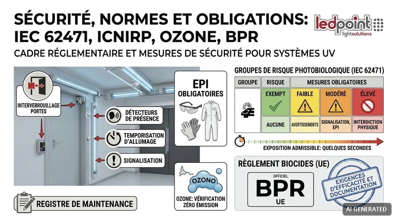
The effective exposure limit commonly adopted for UV radiation in the 180–400 nm range is 30 J/m² (3 mJ/cm²) of effective dose weighted over an eight-hour working day. This value, applied to a typical irradiance from a UV-C fixture, translates into permitted exposure times on the order of seconds or tens of seconds. It is a figure that immediately clarifies why every open UV-C system must have a physical access interlock system.
IEC 62471 risk groups
| Group | Definition | Type of source | Mandatory measures |
|---|---|---|---|
| Exempt (RG0) | No photobiological risk under reasonably foreseeable conditions | Low-power white LEDs | None specific |
| RG1 | Low risk, limited by normal aversion reactions | Many low-power UV-A sources | Informational warnings |
| RG2 | Moderate risk; aversion reaction is not sufficient | Power UV-A strips and bars, intense LED modules | Signage, PPE, access limitation |
| RG3 | High risk even for momentary exposure | All application-power UV-C sources | Physical interlock, interlocks, formalized procedures |
The ten non-negotiable rules of a UV system
Let us summarize in operational form what our technical office considers the minimum baseline for any installation, and what should appear in every specification:
- No UV-C in occupied environments, ever, except closed in-duct systems or upper-room irradiation with certified shielding.
- Door interlocks and presence sensors that turn off the source in less than one second when a person enters. The sensors available in the catalog perform this function in low-voltage configurations.
- Start-up delay of at least 15–30 seconds with acoustic and luminous signaling, to allow evacuation.
- Permanent compliant signage, in Italian and with pictograms, at every access to the irradiated area.
- No controls accessible from inside the irradiated area without protection.
- Mandatory PPE for maintenance: EN 170-certified UV-protective glasses, gloves, full-coverage clothing.
- Formalized AOR risk assessment under Italian Legislative Decree 81/2008 in all workplace contexts.
- Verification of absence of ozone generation: sources emitting below 200 nm generate ozone; if the source is declared ozone-free, it must mount a germanium-doped bulb or suitable filter, and the documentation must attest to it.
- Protection of sensitive materials: polymers, gaskets, cables, textiles, and paints exposed to UV-C degrade; provide UV-resistant materials or shielding.
- Maintenance log with operating hours, replacements, and irradiance checks.
One final commercial but substantial note: if a device is placed on the market claiming to “disinfect,” “sanitize,” or “eliminate bacteria and mold,” that claim falls within the scope of the Biocidal Products Regulation (EU) 528/2012 and requires efficacy documentation. Selling or installing devices with unsupported claims exposes you to significant liability. A UV lighting component sold as a radiant source for technical applications is a different thing from a finished device sold as a biocide: the difference is legal before it is technical, and it is worth being clear about it.
10. Designing a UV system: irradiance, geometry, reflectance, calculations
We now enter the part a designer can use directly. The goal of this chapter is to provide a repeatable sizing method, with formulas, coefficients, and a complete numerical example worked step by step. The method applies to both UV-C and UV-A; only the target dose values change.
From radiant flux to irradiance on the target
Manufacturers of UV LED strips declare the radiant flux per meter, expressed in milliwatts per meter (mW/m). It is the total optical power emitted by one meter of strip, integrated over the entire emission solid angle. For example, the 380 nm UV LED strip at 60 LEDs/m, 24 V, 13.3 W/m declares 750 mW/m of radiant flux, while the 365 nm version with 120 LEDs/m declares 300 mW/m: a difference due to the fact that shorter-wavelength chips have significantly lower quantum efficiencies at the same absorbed electrical power. This confirms what was said above: going down in wavelength costs dearly in output, and it is the main economic reason why UV-C LEDs are still expensive.
To estimate irradiance on a target placed at distance d from a strip of length L, with linear radiant flux Φ' (mW/m), one can use the approximation for a Lambertian linear source:
E (mW/cm²) ≈ (Φ' × kd) / (100 × π × d)
where d is in meters, Φ' in mW/m, and kd is a correction coefficient between 0.5 and 1.0 that accounts for emission directionality (2835 SMD LEDs have 120° Lambertian emission, so typically kd ≈ 0.8 on a frontal target). The formula is valid in the near field, i.e., for d less than about one third of the strip length L; beyond that, decay progressively approaches quadratic.
Complete numerical example
Let us set a real case: we want to keep clean the surface of a 60 cm wide heat exchange coil in an air handling unit, preventing fungal biofilm formation. Target: cumulative dose of at least 1,500 mJ/cm² over 24 hours, a typical value for UVGI coil cleaning systems in continuous operation.
| Step | Quantity | Value | Note |
|---|---|---|---|
| 1 | Target dose over 24 h | 1,500 mJ/cm² | Biofilm prevention, not remediation |
| 2 | Exposure time | 86,400 s | Continuous operation |
| 3 | Required irradiance | 1,500 / 86,400 = 0.0174 mW/cm² | Very low value: time does everything |
| 4 | Source-target distance | 0.30 m | Mounted upstream of the coil |
| 5 | Required linear radiant flux | Φ' = E × 100 × π × d / kd ≈ 0.0174 × 100 × 3.14 × 0.3 / 0.8 ≈ 2.05 mW/m | Practically nothing in UV-C terms |
| 6 | Check with safety factor ×5 | ≈ 10 mW/m | Covers decay, soiling, uncertainty |
This calculation shows a counterintuitive principle of enormous practical value: in continuous operation, impressive cumulative doses are obtained with very low irradiances. This is why UVGI systems permanently installed in AHUs work so well with relatively modest powers, and why, conversely, “pulse” sanitizations with a portable lamp passed for 30 seconds over a surface almost always have disappointing results: 30 seconds at 0.2 mW/cm² gives 6 mJ/cm², a fraction of the dose needed for a melanized fungal spore.
The reflectance factor: the free ally
In a closed cavity, radiation not absorbed by the walls is reflected and contributes again to the dose. The effect is anything but marginal, but it depends on the material, and here lies a classic mistake: reflectances in the visible and in the UV are completely different. A white wall, which reflects 85% in the visible, typically reflects 5–10% in UV-C, because titanium dioxide pigments avidly absorb ultraviolet.
| Material | Visible reflectance | Reflectance at 254 nm | Reflectance at 365 nm | Suitability as UV reflector |
|---|---|---|---|---|
| Specular electropolished aluminum | 85–90% | 70–88% | 80–90% | Excellent |
| Matte anodized aluminum | 75–80% | 45–60% | 60–75% | Good |
| Polished stainless steel | 60–65% | 25–30% | 35–45% | Fair |
| Expanded PTFE (ePTFE) | 95%+ | 90–95% | 95%+ | Excellent but expensive |
| TiO₂ white paint | 80–90% | 5–10% | 10–20% | Very poor: absorbs |
| Light-colored civil plaster | 70–80% | 5–15% | 15–30% | Very poor |
| Glazed ceramic tile | 70–80% | 10–20% | 25–40% | Poor |
| Common float glass | Transparent | Opaque (blocks UV-C) | Partially transparent | Barrier, not reflector |
| Fused quartz | Transparent | Transparent (>90%) | Transparent | Material for UV windows |
The design consequence is clear: when maximum dose must be achieved in a chamber or duct, the internal lining must be electropolished aluminum, not white paint. In a well-reflecting cavity, the dose gain over the direct component alone can exceed 50–80%: it is free power, obtained only by choosing the material. And it is also why aluminum profiles are the natural support for UV strips: they dissipate heat and reflect off-axis radiation.
Thermal management: the parameter that decides useful life
UV LED chips have a more marked dependence on junction temperature than white LEDs, both in terms of instantaneous radiant flux and, above all, long-term decay. As a practical rule, every 10 °C reduction in junction temperature can double the useful life of the device.
For this reason, in every UV installation with LED strips, three construction imperatives apply: always mount on an aluminum profile with full thermal contact along the entire length; never coil on a reel during operation, a condition that quickly pushes chips beyond the thermal limit; no closed diffuser without ventilation, because it traps heat and absorbs UV. The 365 nm UV LED strip at 120 LEDs/m absorbs 14.4 W/m: in a suitable open profile it works quietly for tens of thousands of hours; coiled on a reel it degrades in a few weeks.
Power and control: the current control system
A detail that distinguishes professional strips from cheap ones is the constant-current control system integrated on the PCB. In a traditional voltage-controlled strip, ohmic drop along the trace means the last meters operate at lower voltage and therefore emit less: this is the voltage drop phenomenon, which in the visible range appears as a decrease in brightness and in UV translates into an irradiance gradient and therefore a dose gradient.
Strips with current control (such as the constant-current line in the Ledpoint catalog) keep the current in the LEDs constant within an input voltage range, ensuring uniform emission along the entire run. In UV applications this is not an aesthetic refinement: it is what makes the dose predictable and therefore the project verifiable.
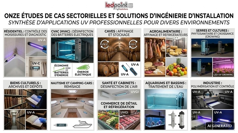
11. Eleven sector case studies with system solutions
We now come to the most operational part of the article. For each sector we describe the specific microbiological problem, the correct UV strategy, the sizing parameters, and the warnings. In each sheet we explicitly indicate when the correct solution is not UV, because a consultant who always proposes the same technology is not advising, he is selling.
Residential: condensation mold in bathrooms, bedrooms, and storage rooms
This is the most widespread case and, paradoxically, the one where UV is least needed. Mold in bathrooms or bedroom corners is almost always the visible effect of a hygrothermal problem: thermal bridge, insufficient ventilation, high vapor production, intermittent heating.
The correct intervention sequence is: measure surface temperature with an infrared thermometer and relative humidity with a hygrometer, calculate the dew point, correct ventilation (localized MVHR with heat recovery, at least 15 l/s in the bathroom), correct the thermal bridge, mechanically remove contaminated material, restore finishes. Only afterward, if residual risk remains, does it make sense to think about UV.
Where UV-A does have an immediate and valuable role is in the diagnostic phase: an inspection bar at 365 nm passed over walls in darkened conditions reveals the real extent of colonization, which is systematically greater than the visible stain. This allows correct sizing of removal, avoiding the classic intervention that leaves the contaminated perimeter behind and brings mold back in six months.
A dedicated note for storage rooms, wardrobe cabinets, and under-stair spaces: here the lack of air exchange and the presence of organic material (textiles, leather, paper) create ideal conditions. A small low-power UV-C module with night timing in a closed and inaccessible compartment, with a door microswitch, is a technically sensible solution; alternatively, a UV-A + TiO₂ module with forced circulation is the safe alternative if the compartment is frequently opened.
HVAC: disinfection of heat exchange coils
This is, without question, the UV application with the best demonstrated efficacy-to-cost ratio in the entire landscape. The cooling coil of an air handling unit is permanently wet from condensation, has an enormous finned surface, operates at temperatures between 6 and 14 °C, and is in the dark: it is the perfect habitat for Cladosporium, Penicillium, and bacterial biofilms.
The biofilm that accumulates between the fins produces three measurable effects: reduced heat exchange and therefore increased electricity consumption of the refrigeration unit on the order of 10–25%, increased pressure drop and therefore fan consumption, continuous emission of spores and odors into the supply air.
The UVGI solution consists of installing UV-C bars upstream of the coil, irradiating it continuously. Operation is 24 hours a day, the cumulative dose is enormous as seen in the numerical example, and the system is intrinsically safe because it is confined inside the machine. The return on investment, considering energy savings and elimination of periodic chemical cleaning, is typically between 12 and 30 months.
| Parameter | Reference value | Note |
|---|---|---|
| Target cumulative dose over 24 h | 1,000–2,500 mJ/cm² | Prevention, not initial remediation |
| Irradiance on the surface | 0.012–0.030 mW/cm² | Very low thanks to time |
| Bar-coil distance | 20–45 cm | Uniformity more important than intensity |
| Position | Upstream side (inlet air) | Also irradiates the condensate pan |
| Materials to protect | EPDM gaskets, PVC cables, filters | Replace with UV-resistant versions |
| Interlock | On all inspection doors | Mandatory |
| Source replacement | 9,000–12,000 h | Not on failure: on decay |
Wine cellars and aging rooms
In oenology the fungal problem has a specificity: high relative humidity is a process requirement, not a defect. A barrel room is typically maintained between 70% and 85% RH precisely to limit evaporation from the wood of the barrels. Under these conditions Penicillium, Cladosporium, and Aspergillus colonize walls, ceilings, external staves, pallets, and equipment.
The risk is not only aesthetic. Some fungal contaminations are associated with the production of chlorinated and brominated anisoles (in particular 2,4,6-trichloroanisole (TCA), responsible for the defect that causes the classic cork taint) which fungi generate by methylating the corresponding phenols present in treated woods, plasters, and construction materials. An environmental TCA contamination in a cellar is an economic disaster, because the compound is perceptible at concentrations of a few nanograms per liter and contaminates the entire production.
The correct UV strategy in a cellar includes:
- night UV-C cycles in the absence of personnel in storage rooms and on wall surfaces, with timers and interlocks;
- in-line UV-C on air treatment circuits if present;
- periodic UV-A fluorescence inspection to monitor the onset of new colonies before they become visible;
- UV-C treatment of the external surfaces of barrels and service materials in a dedicated chamber.
The internal surfaces of barrels, however, cannot be treated with UV for obvious geometric reasons.
Agri-food: curing chambers, refrigerators, and packaging lines
The agri-food sector is where UV technology has the longest application history and the most consolidated regulatory basis. Applications are divided into four fronts.
- Curing chambers for cured meats and cheeses: here fungal flora is partly desired (Penicillium nalgiovense on salami, Penicillium roqueforti in blues) and partly unwanted. UV-C serves to control the airborne load and prevent colonization of technical surfaces and shelves, typically with upper-room irradiation or cycles in the absence of personnel, never on the product, because radiation alters surface lipids, triggering oxidation and rancidity.
- Cold rooms and fruit and vegetable warehouses: the target is Botrytis cinerea and Penicillium expansum, responsible for post-harvest rots. UV-C on recirculated air reduces dissemination. An interesting and documented phenomenon is UV hormesis: low and controlled UV-C doses applied to fruits induce the synthesis of phytoalexins and phenolic compounds in the plant, increasing natural resistance to infections and extending shelf life. It is a refined application that requires precise dosages and validation for each species.
- Packaging lines: UV-C on conveyor belts, packaging film, and machine surfaces, continuously, with integrated shielding. It is one of the most promising UV-C LED applications due to compactness and the possibility of instantaneous switching synchronized with product passage.
- Bakery and pastry: Aspergillus and Penicillium contamination in proofing cells and cooling rooms is a frequent cause of early molding of finished products. Night UV-C cycles in rooms, with smooth and well-reflecting surfaces, produce measurable results on shelf life.
Greenhouses, nurseries, and indoor cultivation
In protected horticulture, UV technology has taken on a role in recent years that goes far beyond disinfection, and it is the sector where the UV-B and UV-A spectrum is exploited for its agronomic properties and not only sanitary ones.
On the phytosanitary front, the main target is powdery mildew and Botrytis. Protocols developed in academia and now applied commercially involve nighttime exposure of crops to low UV-C doses, distributed with mobile carts or motorized suspensions. The key to these protocols is nighttime treatment: the absence of visible light prevents photoreactivation of spores, multiplying efficacy at the same dose. Results reported in the literature indicate reductions in powdery mildew incidence on the order of 70–95% with a drastic reduction in fungicide treatments.
On the agronomic front, controlled exposure to UV-A and UV-B induces the synthesis of secondary metabolites in plants (flavonoids, anthocyanins, essential oils, cannabinoids and terpenes in medicinal crops) with effects on color, aroma, antioxidant content, and commercial value. This is the field for specific products such as the 1-meter Growing LED bar with 36 UV 305–315 nm LEDs and 72 white 3800–4200K LEDs, 48 V ZigBee driver, which integrates the photosynthetic component and the ZigBee-modulatable UV-B component in a single fixture. The ability to control the UV-B channel separately and remotely is what makes a serious agronomic protocol feasible, in which the ultraviolet dose is delivered in precise time windows and measured quantities, instead of being left on at random.
The entire Growing section of the catalog is designed for this type of application, as is the violet chip line, useful where a high-energy violet component is needed to stimulate photomorphogenetic responses without going into true ultraviolet.
Important warning: UV-B treatments on crops require protocols validated for species and cultivar. Excessive doses cause photodamage to the plant, leaf necrosis, and yield reduction. In greenhouses, personnel must also be protected: UV-B is erythemogenic and AOR risk assessment is mandatory.
Cultural heritage: archives, libraries, museum storage
The conservation sector is where UV radiation must be handled with the greatest caution, because the same photochemical mechanism that inactivates spores degrades heritage materials. Paper, parchment, leather, textiles, painting binders, organic dyes: all undergo depolymerization, yellowing, and fading under UV.
International conservation guidelines in fact require the total elimination of the ultraviolet component from exhibition light, with typical limits of 75 µW/lm for sensitive materials. This is exactly why, in museum lighting, LED sources with zero UV emission are chosen, a topic we covered in depth in our guide dedicated to museum lighting with LEDs.
So does UV have no place in cultural heritage? It does, but in three very precise niches, all outside exhibition:
- UV-A fluorescence diagnostics: it is a standard non-invasive investigation technique for identifying retouching, previous restorations, altered varnishes, pictorial integrations, and incipient biological attack. Brief exposures, controlled intensity, under the conservator’s supervision.
- UV-C treatment of storage environments and equipment: in the absence of materials, or on technical surfaces (shelving, carts, benches) during outbreak remediation operations.
- Supply air disinfection: in duct, to reduce airborne fungal load without radiation ever touching objects.
Direct UV-C irradiation of documents, books, canvases, or historical textiles is not a conservatively acceptable practice, except in emergency protocols evaluated case by case by a conservator, and in any case with documented doses and times. Modification of environmental conditions (temperature, humidity, air exchange) should always be preferred, as it is the only truly resolutive intervention.
Marine, camper, and confined mobile environments
The marine environment concentrates all conditions favorable to fungal contamination: permanently high relative humidity, condensation on surfaces in contact with water, no ventilation during winter storage, abundant hygroscopic materials (upholstery, fabrics, woods, carpet), and blind zones such as lockers, bilges, and engine compartments.
The typical result is opening the boat in spring with a penetrating mold odor, stains on fabrics and padding, and contamination of air circuits. The same applies to campers and caravans in winter storage.
The most effective strategy is combined: passive or active dehumidification during storage, timed UV-C cycles in a closed and inaccessible boat, powered at low voltage from the onboard network, with an interlock on the access hatch; UV-A photocatalytic modules for continuous operation in compartments where odor control is desired in the presence of people. In all cases, the 12 V or 24 V power typical of boating naturally matches LED electronics: the 24 V UV strips in the catalog are directly compatible with onboard systems, subject to voltage conditioning with a suitable stabilized power supply.
Note on a version particularly suited to low-voltage systems: the 365 nm UV LED strip at 60 LEDs/m powered at 5 V makes it possible to build portable inspection devices powered by USB power banks, an extremely practical solution for checks in shipyards, lockers, and tight spaces where dragging a mains cable is not feasible.
Healthcare, nursing homes, and clinics
In healthcare, UVGI has an application history of almost a century and a robust body of evidence, particularly for air disinfection in preventing airborne transmission. The consolidated configurations are three.
The first is upper-room UVGI: shielded fixtures installed above 2.1 meters irradiate horizontally only the upper portion of the volume, while the occupied zone remains protected by the optical shield. Air mixing, natural or assisted by ceiling fans, progressively brings the entire volume through the irradiated zone. It is the technique that allows continuous disinfection in occupied environments without Far-UVC, provided the shielding is correctly designed and instrumentally verified.
The second is in-duct UVGI, integrated into air handling systems. The third is terminal room disinfection with high-power mobile devices in the absence of people, typically after patient discharge.
On the specifically fungal front, the most critical issue in healthcare is prevention of invasive aspergillosis in immunocompromised patients, for which primary countermeasures remain HEPA filtration, differential pressurization, and control of adjacent construction sites: UVGI is complementary, not substitutive.
Food retail and commercial refrigeration
In supermarket, deli, and fish shop refrigerated display cases, the problem is twofold: on one hand microbial contamination of surfaces and recirculated air, on the other the need for display light to contain no UV, because ultraviolet radiation accelerates lipid oxidation, myoglobin discoloration in meats, and cheese rancidity.
Correct design clearly separates the two functions: display light with zero UV emission, high CRI, and color temperature calibrated to the product (a topic we explored in the guide on food and LEDs) and UV-C confined in the air circuit and on the evaporator, where no radiation can reach the product or the customer. Mixing the two functions is a mistake that damages both the merchandise and customer trust.
Aquariums, tanks, and water treatment
In aquariology and aquaculture, UV sterilization has been an established practice for decades, and it deserves clarification because requests for UV lamps for aquariums are among the most frequent. In water the target is not molds but unicellular algae, bacteria, protozoan parasites, and fungal zoospores such as those of Saprolegnia, the agent of saprolegniasis in fish.
The principle is identical: dose = irradiance × time, where time is the residence time of water in the irradiated chamber, therefore inversely proportional to pump flow rate. The specific complication is the UV transmittance of water: turbid water, rich in dissolved organic matter or colored by tannins, absorbs radiation and drastically reduces the effective dose. Effective mechanical pre-filtration is not an accessory, it is a prerequisite.
| Objective | Indicative dose | Effect |
|---|---|---|
| Control of suspended algae (green water) | 15–25 mJ/cm² | Flocculation and clarification |
| Bacterial load reduction | 25–35 mJ/cm² | Preventive control |
| Protozoan parasites (free stages) | 90–120 mJ/cm² | Requires low flow rates |
| Fungal zoospores | 100–200 mJ/cm² | Very reduced flow rates |
Warning: UV treatment of aquarium water also reduces beneficial suspended bacteria and can degrade some additives and chelates; it should not be kept on during biological filter maturation cycles or during pharmacological treatments. And, of course, the UV system must always be installed in a closed and watertight chamber, never exposed.
Industry, workshops, and technical environments
We conclude with a range of industrial applications in which ultraviolet performs technical functions adjacent to contamination control.
UV curing of inks, coatings, adhesives, and resins is one of the most mature markets for UV-A LEDs: formulations photoinitiated at 365 nm and 385 nm crosslink in fractions of a second, and LEDs have almost everywhere supplanted mercury lamps thanks to instant start, absence of infrared radiant heat, and the possibility of selective irradiation. Linear UV strips are used in printing machines, bonding lines, and finishing systems.
Fluorescence quality control uses UV-A to verify the continuity of traced adhesives, the uniformity of coatings, the presence of organic contaminants on surfaces before bonding, and the integrity of welds with fluorescent penetrant liquids according to non-destructive testing methods.
Insect light traps exploit the sensitivity peak of insect photoreceptors around 350–370 nm (a topic we explored in detail when discussing the relationship between mosquitoes and the light spectrum) and are mandatory equipment in food companies as part of HACCP plans.
Document and banknote authentication, finally, remains a classic use of 365 nm UV-A in banking, retail, and security sectors.
12. How to build it with Ledpoint products: bill of materials and diagrams
Let us move from theory to the bill of materials. In this chapter you will find the reasoned list of catalog components with which to build professional UV devices, with the selection guidance we provide daily in technical consulting. A clarification: Ledpoint supplies UV-A sources and lighting components at 365 nm and 380 nm and UV-B components for agronomic applications; it does not supply finished biocidal devices or germicidal UV-C sources. The UV-C architectures described in the article must be built with certified germicidal sources and compliant devices, while catalog components fully cover diagnostic, photocatalytic, agronomic, and process functions.
UV sources in the catalog
| Product | λ | Radiant flux | Power | Voltage | LED density | Cutting | Primary application |
|---|---|---|---|---|---|---|---|
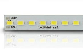
| UV strip 365–370 nm, 120 LEDs/m, current control | 365 nm | 300 mW/m | 14.4 W/m (72 W) | 24 V | 120 LEDs/m | every 5 cm | Professional fluorescence, photocatalysis, long uniform runs |
| UV strip 380 nm, 60 LEDs/m | 380 nm | 750 mW/m | 13.3 W/m (66.5 W) | 24 V | 60 LEDs/m | every 10 cm | High-radiant-flux photocatalysis, polymerization, effects |
| UV strip 365 nm, 60 LEDs/m, 5 V | 365 nm | - | low | 5 V | 60 LEDs/m | - | USB-powered portable tools, inspection in tight spaces |
| Growing bar 1 m, 36 UV-B LEDs + 72 white LEDs, ZigBee | 305–315 nm + 3800–4200K | - | 23 W + 23 W | 48 V | 108 LEDs/m | - | UV-B agronomic protocols, powdery mildew control, secondary metabolites |
How to choose between 365 nm and 380 nm. The rule is simple and worth memorizing. If the goal is to see (fluorescence, diagnosis, quality control, authentication), choose 365 nm, because contrast is higher and the visible veil is lower. If the goal is to deliver photon energy (photocatalysis, polymerization, luminous effects on fluorescent materials), evaluate 380 nm, which at the same absorbed electrical power delivers two and a half times the radiant flux, while still remaining above the activation threshold. In terms of radiant watts per euro, 380 nm is clearly more convenient; in terms of diagnostic quality, 365 nm is irreplaceable.
Mechanics and supports
The support is not an accessory. In a UV installation, the aluminum profile simultaneously performs three technical functions: it dissipates heat, keeping junction temperature low and therefore preserving radiant flux and useful life; it reflects off-axis radiation with UV-A reflectance on the order of 60–90% depending on finish; it mechanically protects the strip from impacts and accidental contact.
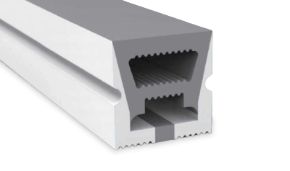
- Aluminum profiles - select sections with wide base and thick wall for UV applications, favoring thermal contact along the entire length.
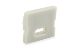
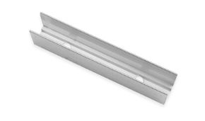
- End caps - essential to avoid radiation leakage from the ends.
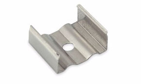
- Mounting clips - reliable mechanical fastening in humid environments, where double-sided tape loses hold over time.
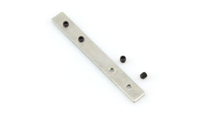
- Profile joints - to create continuous runs without irradiance discontinuities.
- Diffusers - if polycarbonate, they must be avoided in UV applications: they absorb radiation and yellow. They are used only when the UV fixture coexists with a separate visible-light function.
- Custom profiles - for dedicated inspection devices or machine integration, with non-standard geometries.
Power supply
The 24 V UV strips require stabilized power supply sized with margin. The rule we apply is not to exceed 80% of the nominal power supply rating in continuous operation, both for efficiency and for capacitor life.
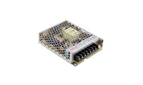
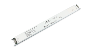
- 24 V power supplies - the standard choice for 24 V UV strips in the catalog.
- 5 V power supplies - for very low voltage versions and portable devices.
- 48 V power supplies - required for the Growing bar with UV-B channel.
- Constant-current power supplies - when driving UV LED modules that require direct current control.
- Power supply accessories - enclosures, terminal blocks, and wiring components.
Control, automation, and safety
The difference between an amateur UV system and a professional one lies almost entirely in control. A UV system must be able to turn on only when safety conditions are verified, must deliver a measurable dose, and must be able to do so repeatably and with logging.
- Monochromatic dimmers - fine adjustment of irradiance; in UV it is mainly used to calibrate dose according to operating distance.
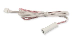
- Sensors - presence, motion, door opening: the heart of safety interlocking.
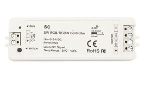
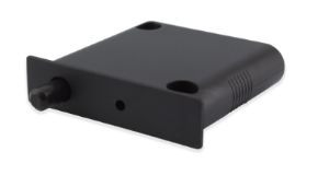
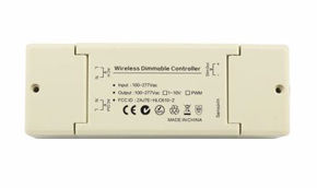
- ZigBee devices - wireless control, timing, scenes, integration into building automation systems, and operating logs.
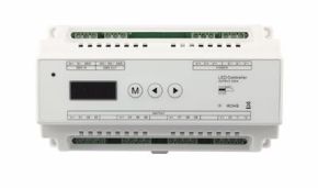
- DMX and DALI decoders - for integration into commercial and industrial systems with central supervision.
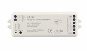
- 0/1-10 V interfaces - for control from PLCs and process controllers.
- Smart power supplies - when power and control are to be concentrated in a single device.
Wiring and accessories
A technical point that is often underestimated: polymeric materials exposed to UV radiation age. PVC sheaths, ABS connectors, double-sided tapes, and silicones not formulated for UV become brittle, yellow, and lose adhesion. In UV installations, it is advisable to position cables and connectors outside the emission cone and to prefer components made of resistant materials.
- Cables of adequate cross-section for voltage drop, sized for long 24 V runs.
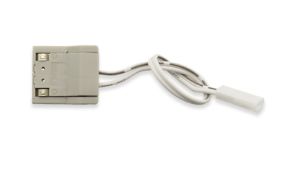
- PCB connectors for LED strips for quick joints; in humid environments, however, soldered joints are preferred, as they are more reliable over time.
- Tapes for LED strips for fastening, verifying compatibility with UV exposure and humidity.
- Tools for cutting, stripping, and proper mounting.
13. Three step-by-step projects ready to replicate
We close the technical part with three possible builds, described so that an installer can execute them without further information. Each project includes objective, bill of materials, procedure, and verification.
Project A - Professional UV-A 365 nm fluorescence inspection bar
Objective: build a diagnostic tool for technical surveys on moisture and fungal contamination, capable of revealing colonies, biofilms, and organic residues not visible to the naked eye.
Bill of materials:
| Component | Quantity | Specification |
|---|---|---|
| UV LED strip 365–370 nm, 120 LEDs/m, current control | 0.6 m | Cut at the 5 cm cutting point |
| Aluminum profile | 0.6 m | Section with base ≥ 12 mm |
| End caps | 2 | One drilled for cable exit |
| 24 V power supply | 1 | ≥ 15 W, or 24 V battery pack for field use |
| Monochromatic dimmer | 1 | For irradiance adjustment |
| Two-core cable | 2 m | 0.75 mm² cross-section |
Procedure: cut the strip exclusively at the marked cutting points, tin the pads and solder the cable, avoiding pin connectors that loosen in mobile use, thoroughly degrease the profile seat with isopropyl alcohol, place the strip applying uniform pressure along the entire length to ensure thermal contact, close with the end caps, do not install a diffuser, connect the dimmer upstream and the power supply. Check uniform illumination and absence of hot spots after 30 minutes of continuous operation.
Operational use: completely darken the environment, wait 3–5 minutes for visual adaptation, maintain a distance of 20–40 cm from the surface, move the bar slowly with a grazing motion. Wear UV-protective glasses and never point the source toward people. Photograph with long manual exposure and fixed white balance for documentation comparable between surveys.
Project B - UV-A photocatalytic module for air duct
Objective: build a photocatalytic oxidation stage installable in an air duct or recirculation box, for continuous control of MVOCs, mold odors, and airborne microbial load, with safe operation in the presence of people.
Bill of materials: UV LED strip 380 nm 60 LEDs/m (to maximize radiant flux) in a length equal to the useful perimeter of the chamber, aluminum profiles for mounting and dissipation, catalytic element with honeycomb or mesh coated in anatase TiO₂, with high specific surface area, 24 V power supply sized with 25% margin, flow sensor or auxiliary contact from the fan for operation interlock, internal lining in electropolished aluminum.
Sizing criteria:
| Parameter | Reference value | Rationale |
|---|---|---|
| Air velocity in the chamber | 1.0-2.5 m/s | Sufficient contact time |
| Irradiated chamber length | ≥ 40 cm | Residence time ≥ 0.2 s |
| Irradiance on the catalyst | 1-5 mW/cm² | Below 1 mW/cm² performance collapses |
| LED-catalyst distance | 3-8 cm | Compromise between irradiance/uniformity |
| Post-filtration | Activated carbon recommended | Captures any by-products |
| Catalyst replacement | 12-24 months | Progressive poisoning |
Verification: measure total VOC concentration downstream before and after activation with a PID instrument, and verify absence of aldehyde increase. If the module produces aldehydes, it is undersized: increase catalytic surface area or reduce flow rate.
Project C - Modulated UV-B system for powdery mildew control in greenhouse
Objective: implement a nighttime UV-B irradiation protocol on protected crops to reduce powdery mildew incidence and dependence on fungicides, with digital control of the time window and intensity.
Bill of materials: Growing LED bars with separate UV-B 305-315 nm and white channels, in number and spacing according to bay width, 48 V power supplies, ZigBee gateway and devices for cycle programming, height-adjustable suspensions, safety signage at accesses.
Reference operating protocol (always to be validated on the individual cultivar with pilot plot trials):
- Time window: irradiation in the central hours of the night, in total absence of visible light, to prevent photoreactivation.
- Frequency: 3-5 nights per week, not every night, to limit stress on the crop.
- Duration: start with short exposures (a few minutes) and increase gradually, monitoring leaf condition.
- Height: keep the distance from the vegetative apex constant by compensating growth with adjustable suspensions; irradiance varies significantly with distance.
- Monitoring: untreated control plots, weekly assessment of incidence and severity, phytotoxicity assessment.
- Safety: no personnel access during cycles; door interlock; permanent signage; AOR risk assessment.
Warning, this is the critical point of the entire project: the UV-B channel must always be driven separately from the white channel. A system in which UV-B turns on together with growth light is simultaneously less effective (due to photoreactivation) and more risky for the crop and personnel. This is exactly why a bar with a ZigBee driver separately addressable on the two channels is worth, in this application, much more than its premium.
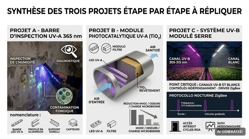
14. UV versus alternative methods: comparison table
No technology is best in absolute terms. This table compares ultraviolet with the alternatives actually available, with their advantages and limitations, because the correct choice depends on the context.
| Method | Efficacy on spores | Penetration into substrate | Use in presence of people | Residues | Operating cost | Preferred context |
|---|---|---|---|---|---|---|
| Hygrothermal control (dehumidification, MVHR, insulation) | Totally preventive | Not applicable | Yes | None | Medium | Always: it is the basis of everything |
| Mechanical removal | Total on removed material | Total | With PPE | None | High (labor) | Remediation of existing colonization |
| Germicidal UV-C | High on surfaces | None | No (except upper-room or in-duct) | None | Low | HVAC, air, smooth surfaces, maintenance |
| Far-UVC 222 nm | Medium on fungal spores | None | Yes (with limits) | Ozone/secondary particulate | High | Crowded environments, airborne pathogens |
| UV-A + TiO₂ photocatalysis | Low-medium, continuous | None | Yes | Possible aldehydes if poorly designed | Low | Odors, MVOCs, maintenance in occupied environments |
| Sodium hypochlorite | High | Poor | No | Chlorinated by-products, corrosion | Very low | Smooth washable surfaces |
| Vaporized hydrogen peroxide | Very high | Medium | No | Decomposes into water and oxygen | High | Terminal remediation, cleanrooms |
| Ozone | High | Medium in gas phase | No, toxic | Material oxidation | Low | Extraordinary remediation, with post-treatment clearance |
| Biocidal formulated products | High | Medium | No | Persistent chemicals | Medium | Wall treatments, porous surfaces |
| HEPA filtration | Removal, not inactivation | Not applicable | Yes | None | Medium | Airborne load reduction |
The summary in one line: hygrothermal control is always the first intervention, mechanical removal is the only way to eliminate existing colonization, UV is the best technology for continuous maintenance and for air, chemistry serves extraordinary remediation. Anyone proposing a single technology as a universal solution is oversimplifying beyond what is permissible.
15. Ten mistakes that defeat a UV system
This section collects the mistakes we see most frequently in installations submitted to us for verification. They are all mistakes that can be prevented at the design stage at zero cost and that, once the system is built, cost a lot.
- Confusing the bands: buying 395 or 405 nm LEDs expecting germicidal action. As seen, relative germicidal efficacy at those wavelengths is less than one thousandth of the peak. The product works very well for what it is made for (fluorescence, effects, photocatalysis with a suitable catalyst) but does not sterilize anything.
- Thinking in watts instead of dose: absorbed electrical power says nothing about efficacy. You need radiant flux, irradiance on the target, and time. A 5 W system running 24 hours far outperforms a 100 W system turned on for thirty seconds.
- Ignoring geometric shadows: UV does not turn corners. Every surface not in direct view of the source receives only the reflected component, which on building materials is almost nothing. Backs of furniture, undercuts, folds of fabric: free zones.
- Using white paint as a reflector: in the visible it reflects 85%, in UV-C 5%. You need aluminum, not paint.
- Mounting the strip without an aluminum profile: thermal decay reduces radiant flux and useful life dramatically and silently: the system seems to work, but the delivered dose progressively falls.
- Installing an opal diffuser: it absorbs UV radiation, yellows, and reduces system efficacy without anyone noticing.
- Omitting interlocks: this is the most serious mistake of all: a UV-C system without a door sensor and without start delay, in an accessible room.
- Neglecting surrounding materials: gaskets, cables, filters, and polymer components exposed to UV-C degrade in months. They must be UV-resistant or shielded.
- Not planning maintenance: a UV source at end of life may still emit visible light (if it emits any) but has lost much of its useful radiant flux. Without an hours log and periodic measurement, the system dies unnoticed.
- Treating the effect instead of the cause: installing UV on a wall that molds because of an unresolved thermal bridge means spending money to move the problem a few months later. First dry, then remediate, then maintain.
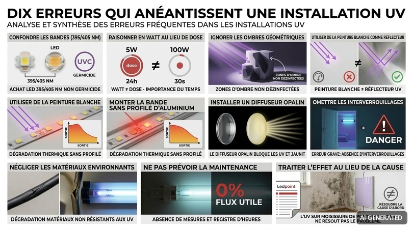
16. Costs, consumption, and return on investment
A technical project is also judged on its economic account. This section provides orders of magnitude for building a realistic assessment, with the caveat that values depend on market, scale, and specifications.
| Configuration | Power | Hours/year | kWh/year | Energy cost/year |
|---|---|---|---|---|
| 0.6 m inspection bar, occasional use | 8.6 W | 100 | 0.9 | 0.22 € |
| 1 m photocatalytic module, continuous | 13.3 W | 8,760 | 116 | 29 € |
| 2 m photocatalytic module, continuous | 26.6 W | 8,760 | 233 | 58 € |
| Greenhouse system 10 Growing bars, UV-B channel 3 nights/week × 30 min | 230 W (UV-B only) | 78 | 18 | 4.50 € |
| Greenhouse system 10 bars, white channel 12 h/day | 230 W | 4,380 | 1,007 | 252 € |
The striking figure is that the energy cost of ultraviolet is almost always negligible compared with the value of what it protects. A photocatalytic module consuming 29 € per year in energy protects an environment whose mold remediation would cost thousands of euros. A UV-B channel in a greenhouse costs 4.50 € per year in electricity and can significantly reduce fungicide treatments on a crop worth tens of thousands of euros per bay.
| Application | Typical investment | Estimated annual benefit | Indicative payback |
|---|---|---|---|
| UVGI on HVAC coil (medium AHU) | 1,500–4,000 € | Energy + cleaning: 1,000–3,000 € | 12–30 months |
| UV-A inspection bar for remediation company | 150–400 € | Diagnosis quality, reduced warranty returns | 1–2 interventions |
| Photocatalytic module in recirculation | 400–1,200 € | Reduced odors and complaints, fewer sanitizations | 18–36 months |
| UV-B greenhouse system (per bay) | 2,000–6,000 € | Reduced fungicides + lower losses | 18–48 months |
| Night UV-C cycles in cellar | 1,000–5,000 € | Contamination prevention, reduced TCA risk | Insurance rather than economic |
17. Maintenance, decay, and field measurement
A UV system is a process system, not a lighting system. The substantial difference is that lighting is verified with the eyes, UV is not: a degraded source continues to look identical while delivering half the dose. For this reason, scheduled maintenance is not optional.
Radiant flux decay
UV LEDs decay faster than white LEDs, for reasons related to degradation of encapsulating materials under high-energy radiation and the higher current densities typical of these devices. The parameter to watch is L70, i.e., the time after which radiant flux falls to 70% of initial value.
| Technology | Indicative L70 | Loss at half life | Recommended verification frequency |
|---|---|---|---|
| UV-A LED 365-380 nm, well heat-sinked | 20,000-50,000 h | 10-15% | Annual |
| UV-A LED poorly heat-sinked | 3,000-8,000 h | 30-40% | Semiannual |
| UV-C LED 275 nm | 5,000-15,000 h | 20-25% | Semiannual |
| Low-pressure Hg lamp | 8,000-16,000 h | 20-30% | Annual, scheduled replacement |
Cleaning: the most underestimated factor
A film of dust on a quartz tube or LED chip can cut useful emission by 30-50%. In dusty environments, periodic cleaning of optical surfaces produces a dose recovery greater than any power upgrade, at practically zero cost. Cleaning must be performed with the system off and cold, using isopropyl alcohol and a lint-free cloth, without touching the chips with bare hands because skin oils carbonize under UV, forming permanent deposits.
Measure, do not estimate
Serious verification is done with instruments. The options are three, in increasing order of cost:
- Single-use chemical dosimeters: labels that change color upon reaching a threshold dose. Inexpensive, immediate, semi-quantitative. Excellent for verifying geometric coverage: place about ten in different points and immediately identify shadow zones.
- UV radiometers with a sensor calibrated to the band of interest. They provide irradiance in mW/cm² and allow direct dose calculation. The sensor must be calibrated to the actual wavelength of the source: a radiometer calibrated at 254 nm gives meaningless readings on a 365 nm source.
- Biodosimetry: exposure of indicator microorganisms to a known dose and counting survivors. It is the reference method for validation, requires a laboratory, and is justified in agri-food, pharmaceutical, and healthcare settings.
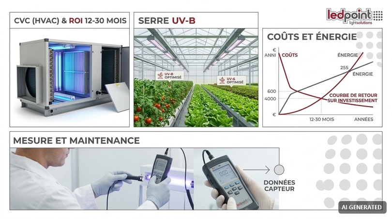
18. Operational project checklist
Let us summarize the entire path in a checklist that can be used directly as a specification outline or as a verification of an offer received from third parties.
| Phase | Verification | Acceptance criterion |
|---|---|---|
| Diagnosis | Cause of moisture identified and quantified | Surface temperature, RH, dew point survey |
| Diagnosis | Real extent of contamination mapped | UV-A fluorescence inspection and, if necessary, sampling |
| Remediation | Colonized material removed | Removal beyond the visible perimeter |
| Design | Correct UV band for the objective | UV-C for germicidal, UV-A for diagnosis/photocatalysis, UV-B for agronomy |
| Design | Target dose defined in mJ/cm² | Referred to the most resistant target species present |
| Design | Irradiance and time calculated and verified | With safety factor ≥ 1.5 and humidity correction |
| Design | Geometry free of critical shadow zones | Verification with dosimeters at at least 8 points |
| Design | Internal reflectance optimized | Aluminum, not white paint |
| Construction | Adequate thermal dissipation | Aluminum profile, full contact, no coil |
| Construction | No absorbing diffuser in line | Open profile or quartz/suitable glass window |
| Construction | Surrounding materials UV-resistant | Cables, gaskets, and connectors suitable or shielded |
| Safety | Interlocks on all accesses | Shutdown < 1 s |
| Safety | Start delay and signaling | ≥ 15 s with acoustic and luminous warning |
| Safety | Signage and PPE available | Compliant and in Italian |
| Safety | AOR risk assessment | Documented under Italian Legislative Decree 81/2008 |
| Operation | Operating hours log active | With scheduled replacement threshold |
| Operation | Optics cleaning plan | Frequency defined according to environment |
| Operation | Periodic irradiance verification | Radiometer calibrated to the correct band |
19. Frequently asked questions
Here we collect the questions we receive most often from our technical office, with concise and verifiable answers. Each answer is designed to be directly usable as a decision criterion.
Do 365 nm or 395 nm UV LEDs kill mold?No, not directly. Germicidal efficacy at 365 nm is less than one thousandth of that at the 265 nm peak. UV-A LEDs are very useful for revealing colonies through fluorescence and for driving photocatalytic systems based on titanium dioxide, which produce oxidizing radicals, but they are not germicidal sources. Direct inactivation requires the UV-C band. |
What is the practical difference between 365 nm and 380 nm?365 nm emits very little visible light and therefore offers the best contrast in fluorescence: it is the choice for diagnosis and quality control. 380 nm delivers a much higher radiant flux at the same absorbed power (750 mW/m versus 300 mW/m in the catalog versions) and is more convenient when photon energy is needed for photocatalysis or polymerization. |
How much UV-C dose is needed to inactivate mold spores?It depends on the species. For Penicillium, approximately 60–130 mJ/cm² is needed for 2 log; for Cladosporium, 140–280 mJ/cm²; for Aspergillus niger, even 250–500 mJ/cm². Melanized black molds are the most resistant. In very humid environments the dose must be increased by a factor of 1.5–3. |
Can I use a UV-C lamp at home while I am present?Absolutely not. UV-C radiation causes photokeratitis and erythema with symptoms that appear hours after exposure, so there is no immediate perception of damage. The only configuration usable in the presence of people is upper-room irradiation with certified shielding, or systems completely confined in duct. |
Does UV eliminate the black mold stain on the wall?No. UV can inactivate surface spores and stop sporulation, but it does not remove biomass or pigment. The stain remains and material colonized in depth is not reached, because UV does not penetrate opaque materials. Mechanical removal remains indispensable. |
Does UV destroy mycotoxins?Only partially and with very high doses, well above those for microbial inactivation. An inactivated spore also remains an allergenic body. For this reason UV should be considered a control and maintenance system, not a complete health remediation method. |
Why is nighttime treatment more effective?Because many microorganisms have photolyase, enzymes that repair pyrimidine dimers using the energy of blue and UV-A light. In the absence of visible light after irradiation, repair is strongly slowed and the same dose produces markedly higher inactivation. |
Is the aluminum profile also needed for UV strips?It is needed more than for white strips. UV chips have performance and useful life strongly dependent on junction temperature: every 10 °C reduction can double lifespan. The profile dissipates heat, reflects off-axis radiation, and provides mechanical protection. The opal diffuser, by contrast, must be avoided because it absorbs UV and yellows. |
Do white walls reflect UV and help treatment?No, and it is one of the most common mistakes. White paints contain titanium dioxide, which strongly absorbs ultraviolet: reflectance at 254 nm falls to 5–10% versus 85% in the visible. If UV reflection is needed, use electropolished aluminum, which reflects 80–90% at 365 nm. |
Is TiO₂ photocatalysis safe in the presence of people?Yes, if the system is correctly designed and UV-A radiation is confined inside the device. The risk to manage is not radiation but the possible formation of aldehydes from incomplete oxidation in undersized systems or with exhausted catalyst. Adequate catalytic surface, sufficient contact times, activated carbon post-filtration, and scheduled replacement of the element are required. |
Does UV in a greenhouse replace fungicides?It reduces them, it does not automatically replace them. Nighttime UV-C and UV-B irradiation protocols documented in the literature show important reductions in powdery mildew incidence, but they must be validated for species and cultivar, precisely dosed to avoid phytotoxicity, and inserted into an integrated pest management strategy. |
How long do UV LEDs last?A well heat-sinked UV-A strip on an aluminum profile typically reaches 20,000–50,000 hours at L70. The same strip mounted poorly, without heat dissipation or left on a reel, can drop to a few thousand hours. UV-C LEDs have shorter lives, on the order of 5,000–15,000 hours. |
How do I verify that my system is working?With single-use chemical dosimeters to verify geometric coverage and with a radiometer calibrated to the source band to measure irradiance. Visual inspection alone says nothing: a degraded source looks identical to a new one while delivering half the dose. |
Does UV produce ozone?Only sources emitting below 200 nm, typically at 185 nm. 254 nm lamps with doped bulbs and UV-C LEDs at 265–285 nm do not generate ozone. Far-UVC sources at 222 nm can trigger secondary air chemistry. Always verify the manufacturer’s ozone-free declaration. |
Can I irradiate books, paintings, or archival documents with UV-C?No, it is not a conservatively acceptable practice. The same radiation that inactivates spores degrades paper, inks, binders, and dyes. In cultural heritage, UV-A is used for fluorescence diagnostics at brief exposures, while microbiological control is addressed with climate management, filtration, and in-duct air treatment. |
Which UV application has the best economic return?Continuous irradiation of heat exchange coils in air handling units. Biofilm on fins reduces heat exchange by 10–25% and requires periodic chemical cleaning; a UVGI system confined inside the machine works 24 hours a day with very low irradiances and typically pays for itself in 12–30 months. |
UV LEDs and molds: using ultraviolet competently
Ultraviolet radiation is a powerful and mature tool for controlling fungal contamination, provided three technical truths are respected: it acts only on what it sees, it acts only as a function of dose, and it acts only if the cause of moisture has been resolved. Respect these three conditions, and UV maintains results that no other technology maintains with the same continuity and the same operating cost. Ignore even one of them, and it is money spent on a system that produces no measurable results.
For the designer, the installer, and the company that wants to build serious solutions, the path is traced: diagnose with UV-A at 365 nm, maintain with photocatalysis where there are people, inactivate with UV-C where there are none, modulate with UV-B where there is a crop to manage, and in every case design with calculated doses, correct materials, and non-negotiable safety.
Our technical office is available for custom sizing of UV-A and UV-B systems. You can explore the range of ultraviolet LED strips, the Growing section for agronomic applications, the aluminum profiles for correct mounting, and the appropriate power supplies, or contact us directly for advice on your project.
This article was developed with the support of artificial intelligence and subsequently reviewed, corrected, and validated by the Ledpoint.it technical team, which guarantees its reliability and conformity with official sources.