


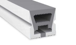

The DALI system (Digital Addressable Lighting Interface) is a digital communication protocol standardized by the IEC 62386 standard that allows for addressable, scalable, and bidirectional control of every single lighting fixture connected to the bus. Unlike traditional analog systems, the DALI system allows assigning a unique address to each device, adjusting its light intensity with 256-level resolution, creating custom groups and scenes, and integrating the system with home automation and the most advanced building automation systems.
In this technical guide, we will aim to comprehensively answer all the questions that designers, lighting designers, electrical installers, system integrators, architects, interior designers, technical managers of shops, hotels, museums, pastry shops, congress centers, and bus operators ask when approaching a modern DALI system for the first time (or when they need to update their skills on it). We will cover what the DALI system is, how the DALI system works, how to connect DALI, how the DALI protocol is structured, the differences between DALI and DALI-2, how to use the DALI system with LED strips, power supplies, controllers, DALI dimmers, and smart gateways, and which DALI-compatible products are selected in the Ledpoint catalog.
The goal is to offer a single, updated resource for 2026 that can become your reference whenever you are looking for information on the DALI system, DALI protocol, DALI wiring diagrams, DALI dimmers, DALI technology, DALI interface, how the DALI system works, LED lighting systems based on DALI, or DALI integration with Skydance, Tuya, Zigbee, WiFi, Alexa, and Google Home. Most of the products mentioned in this guide are available in the Ledpoint.it catalog or can be ordered with free technical consultancy, complete datasheets, wiring diagrams, and commissioning support.
In this article...
1. What is the DALI system: definition, history, and IEC 62386 standard
The DALI system, acronym for Digital Addressable Lighting Interface, is the de facto standard digital communication protocol for professional lighting control worldwide. When a designer, installer, or client talks about the "DALI system", "DALI protocol", "DALI interface", "DALI technology", or "DALI lighting system", they are referring to the same regulatory family: the IEC 62386 series, published and maintained by the International Electrotechnical Commission, which uniquely regulates the electrical behavior, logical level, command format, and addressing mechanisms of all DALI-compatible devices placed on the market.
In other words, the DALI system is a common language that makes LED power supplies, DALI dimmers, sensors, buttons, touch panels, gateways, masters, and slaves from different brands talk to each other, without any of them having to be custom-designed for the specific installation. This is the fundamental difference between a DALI system and traditional lighting: in the DALI system, every device is an intelligent node, equipped with an internal microcontroller, capable of receiving digital commands, executing them, and (in DALI-2 versions) returning status information to the master.
Origins of the DALI system: from the 1990s to the modern DALI protocol
DALI technology was born in the late 1990s as an evolution of the previous 1-10V analog system, which had severe limitations: non-addressable commands, polarity to be respected, impossibility to assign scenes, no diagnostics, and sensitivity to electrical disturbances. The European lighting industry, led by manufacturers such as Osram, Philips, Tridonic, Helvar, and Vossloh-Schwabe, proposed the first DALI system as an open standard with the publication of IEC 60929 Annex E, which was later incorporated into the IEC 62386 series starting in 2009.
Since 2014, the DALI Alliance consortium (previously AG DALI, now DiiA - Digital Illumination Interface Alliance) has introduced the DALI-2 brand, which certifies full interoperability between devices from different manufacturers and introduces new features such as color control, management of input sensors on the same bus, status reporting, and energy diagnostics. Today, when talking about the DALI system in a new installation, one is almost always talking about DALI-2, because the DALI-2 logo guarantees the designer that the device has been tested and certified according to the IEC 62386 standard in force.
Practical meaning of the DALI and DALI-2 logos
A specific logo appears on products compatible with the DALI system: the classic DALI logo identifies devices compliant with the first version of the DALI protocol, while the DALI-2 logo (a square with the wording DALI-2) identifies devices certified by the DALI Alliance after passing the official certification program. For the client and the designer, choosing products with the DALI-2 logo means having the guarantee that the device will work on any DALI bus without compatibility issues, regardless of the master, gateway, or power supply used.
Ledpoint exclusively selects in its catalog products compliant with the latest revisions of the IEC 62386 standard and, for most DALI controllers, DALI-2 certified. This technical choice protects the client from interoperability problems, which historically have been one of the main critical issues of digital lighting systems in the early 2000s.
Why it is called "Addressable": the meaning of addressing
The keyword in the name of the DALI system is "Addressable". In a DALI system, every device receives a unique numerical address between 0 and 63, which identifies its logical position on the bus independently of its physical position in the wiring. This means that, once the system is installed and addressed, it is possible to physically move the device (within the electrical limits of the bus) without having to reconfigure anything, and it is possible to reassign groups and scenes via software without touching a single wire.
This paradigm is revolutionary compared to traditional wiring: in a classic system, two lamps controlled by the same switch must be physically connected in parallel to that circuit; in a DALI system, any two of the 64 lamps on the bus can be dynamically associated with the same button simply by modifying the software configuration. This is the real reason why the DALI system is the reference technology in lighting projects that require flexibility over time, such as open-plan offices, showrooms, retail, hotels, museums, congress centers, restaurants, pastry shops, and any environment where the lighting layout needs to be redesigned without masonry work.
The three conceptual pillars of the DALI system
To deeply understand what the DALI system is, it is convenient to fix three key concepts that we will find throughout the article:
| Pillar | What it means in the DALI system | Design implication |
|---|---|---|
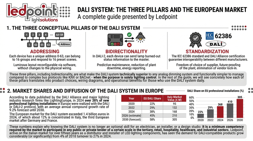
| Addressing | Each device has a unique address 0–63, can belong to 16 groups, and respond to 16 predefined scenes. | Lighting layout reconfigurable via software, without changes to physical wiring. |
| Bidirectionality | In DALI-2, every device can send status information to the master (burnt lamp, driver error, operating hours). | Predictive maintenance, reduction of system downtime, energy reporting. |
| Standardization | IEC 62386 standard and DALI Alliance certification guarantee interoperability between different manufacturers. | Freedom of supplier choice, future-proofing of the system, elimination of vendor lock-in. |
These three pillars (addressing, bidirectionality, standardization) are what make the DALI system technically superior to any analog dimming system and functionally simpler to manage compared to complex bus protocols like KNX or BACnet when the sole purpose is lighting control. In the rest of the guide, we will see concretely how each of these pillars translates into product choices, connection diagrams, and operational benefits for those who use the DALI system daily.
Market share and diffusion of the DALI system in Europe
According to data published by the DALI Alliance and the main research companies in the lighting sector (LightingEurope, IHS Markit, Guidehouse Insights), in 2024 over 38% of new professional lighting installations in Europe were realized with the DALI or DALI-2 protocol, with a compound annual growth rate of 9.2% expected until 2030. The European market for the DALI system exceeded 1.4 billion euros in 2024, of which about 12% is concentrated in Italy, the third European market after Germany and France.
| Year | DALI share on EU professional installations | DALI market value Italy (€ mln) |
|---|---|---|
| 2020 | 22% | 95 |
| 2022 | 29% | 132 |
| 2024 | 38% | 168 |
| 2026 (estimate) | 45% | 210 |
| 2030 (forecast) | 58% | 305 |
These numbers explain why knowing the DALI system is no longer an optional skill for an electrician, installer, or design studio: it is a minimum skill required by the market to participate in any public or private tender of a certain size in the tertiary, retail, hospitality, healthcare, and industrial sectors. Ledpoint, active in the Italian market for over fifteen years as a distributor and installer of LED lighting components, has seen the demand for DALI-compatible products grow from 4% of turnover in 2018 to 27% in 2024.
2. How the DALI system works: bus, addressing, digital commands
Understanding how the DALI system works means understanding four fundamental technical elements: the DALI bus (the physical medium), the DALI protocol (the language), DALI addressing (the directory of nodes), and the flow of DALI commands (the conversation between master and slave). In this chapter, we will see in detail how each of these elements operates within the DALI system and what changes compared to traditional lighting systems and non-DALI LED lighting systems.
The DALI bus: two wires, an entire network
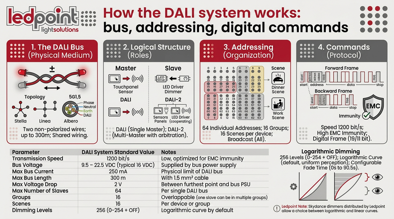
The DALI bus is the physical backbone of the DALI system. It consists of two non-polarized conductors that simultaneously carry the service power (about 16 VDC) and the digital communication signal at 1200 bit/s, superimposed as voltage modulation. The DALI bus can extend up to a maximum length of 300 meters with a 1.5 mm² cross-section cable, without the need for terminations or particular topologies: the DALI system accepts star, line, tree, or mixed wiring, as long as the maximum length and the maximum bus current of 250 mA are respected.
One of the distinctive features of the DALI system is non-polarity: the two wires of the DALI bus can be reversed without compromising operation. This detail, seemingly trivial, is one of the reasons why the DALI system has been hugely successful on construction sites: the installer does not have to worry about respecting a direction, drastically reducing the probability of wiring errors compared to 0-10V or 1-10V systems which are polarized. In the DALI system, the bus can also be laid in the same multipolar cable as the mains power: modern 5G1.5 or 5G2.5 cables at 450/750 V can safely carry phases, neutral, earth, and DALI bus on the same bundle.
The logical structure of the DALI system: master and slave
In the DALI system, every device has a precise logical role. DALI master devices are those that send commands on the bus: typically touch panels, keypads, home automation gateways, presence/luminosity sensors (in DALI-2), or programmable controllers. DALI slave devices are those that receive commands and execute them: LED power supplies, drivers, DALI dimmers, decoders for LED strips, DALI relays. A traditional DALI bus admits only one master speaking at a time, but multiple masters can coexist as long as only one master transmits at a time.
In DALI-2, this model has been extended by introducing multi-master: multiple masters can coexist on the same DALI bus with an arbitration mechanism that avoids collisions. This is why in DALI-2 it is possible to have a touch panel, a presence sensor, and an ambient light sensor all on the same DALI bus simultaneously, and make them cooperate in the dynamic management of light based on the real conditions of the environment.
DALI addressing: 64 individual addresses, 16 groups, 16 scenes
The functional heart of the DALI system is addressing. Up to 64 individually addressable slave devices can coexist on each DALI bus, organized into 16 DALI groups and with 16 predefined DALI scenes for each device or group. Let's see what this means concretely:
- DALI individual address: each device has a number from 0 to 63 that uniquely identifies it. A "set brightness to 50%" command sent to address 12 will be executed only by the device that bears that address.
- DALI group address: each device can simultaneously belong to one or more of the 16 available groups. A command sent to group 3 will be executed by all devices that are part of group 3.
- DALI broadcast: a broadcast command is executed by all devices on the bus simultaneously. Useful for general on/off or reset.
- DALI scenes: each device stores up to 16 scenes, each associated with a brightness level (and in DT8 also a color). Recalling "scene 5" means bringing all devices in the scene to the stored settings.
This addressing scheme is what makes the DALI system extremely powerful for applications where the same lamp must be able to be controlled in multiple ways: in the DALI system, the same light can respond to a local button, a room scenario, a broadcast emergency command, and a presence sensor simultaneously, without the physical wiring having to provide for any of these cases in a dedicated way.
DALI commands: how a digital frame is structured
At the protocol level, every DALI command is a 19-bit digital frame (forward frame) for master→slave commands, and 11 bits (backward frame) for slave→master responses in DALI-2. The frame contains: a start bit, 8 address bits (with flags distinguishing individual address, group address, or broadcast), 8 command or data bits, and 2 stop bits. The deliberately low speed of 1200 bit/s guarantees excellent immunity to electrical disturbances and allows the DALI system to work in noisy environments such as industries, warehouses, machine rooms without the need for special shielding of the bus cable.
| Parameter | Standard DALI system value | Notes |
|---|---|---|
| Transmission speed | 1200 bit/s | Low, optimized for EMC immunity |
| Bus voltage | 9.5 – 22.5 VDC (typical 16 VDC) | Supplied by the bus power supply |
| Maximum bus current | 250 mA | Physical limit of the DALI bus |
| Maximum bus length | 300 m | With 1.5 mm² cable |
| Max voltage drop | 2 V | Between furthest point and bus PSU |
| Maximum number of slaves | 64 | Per single DALI bus |
| Groups | 16 | Overlapping (one slave can be in multiple groups) |
| Scenes | 16 | Per device or group |
| Dimming levels | 256 (0–254 + OFF) | Default logarithmic curve |
DALI system dimming resolution: 256 logarithmic levels
A often underestimated feature of the DALI system is the dimming resolution. The DALI standard provides for 256 brightness levels (0–254 plus the OFF condition) distributed on a logarithmic curve that simulates the perception of the human eye: the eye perceives light variations in a non-linear way, and a logarithmic curve allows for perceptually uniform variations between one level and the next. This eliminates the "stepping" of brightness typical of cheap analog dimmers and makes the DALI system ideal for sensitive environments such as restaurants, conference rooms, pastry shops, museum environments, and anywhere the quality of the light transition is part of the user experience.
Some modern DALI dimmers — including the Skydance models distributed by Ledpoint — allow selecting via software between the logarithmic curve (default DALI) and the linear curve (useful for cinematic applications or laboratory tests). The fade transition between two brightness levels in the DALI system is also configurable, with fade times from 0 seconds (instant change) up to 90.5 seconds, divided into 16 standard fade times.
3. DALI vs DALI-2: differences, advantages, backward compatibility
The question "what is the difference between DALI and DALI-2?" is probably the most frequent we receive from professional clients approaching a modern DALI system for the first time. DALI-2 is the evolution of the classic DALI (DALI v1), released by the DALI Alliance to overcome the limits of the first-generation DALI and to offer certified interoperability between different manufacturers. Let's see in detail what changes, when it is convenient to choose DALI-2, and when the classic DALI is still sufficient.
DALI v1: the limits of the first-generation DALI system
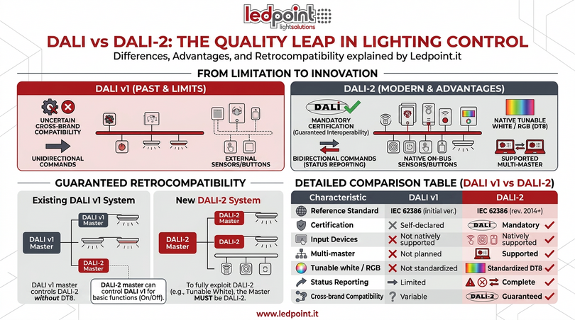
The first-generation DALI system, although it was a huge step forward compared to analog control, had some limitations that over time became concrete obstacles to its diffusion. The first limitation was uncertain compatibility: despite the IEC 62386 standard being public, manufacturers implemented it with small differences that generated interoperability problems when mixing different brands on the same DALI bus. The second limitation was the unidirectional nature of the commands: in DALI v1, the bus was designed to send commands from the master to the slaves, but there was no standardized way to receive return information from the slaves. The third limitation was the lack of support for input devices on the same bus: buttons, presence sensors, and light sensors had to be connected to separate controllers that then in turn communicated on the DALI bus as masters.
DALI-2: the qualitative leap of the modern DALI system
DALI-2, formalized in the most recent revisions of IEC 62386 (parts 101, 102, 103, 207, 208, 209, and following), systematically solves these limitations. The main innovations of DALI-2 compared to DALI v1 are five:
- Mandatory DALI Alliance certification: no manufacturer can affix the DALI-2 logo on its products without passing the DALI Alliance certification tests, which verify full compliance with the standard. This eliminates the compatibility problem of DALI v1.
- Native support for input devices: in DALI-2, sensors and buttons are first-class devices on the bus, with their own addresses and commands, and can coexist with output slaves on the same DALI bus.
- Status reporting: every DALI-2 device can send information to the master such as burnt lamp, driver error, operating hours, internal temperature, energy consumption.
- Tunable White and RGB (DT8): DALI-2 introduces device type 8, which natively manages sources with variable color temperature (TC), RGB, RGBW, RGB+CCT, xy color, and color primary N.
- Multi-master: DALI-2 admits multiple masters on the same bus with automatic arbitration, eliminating the need for intermediate gateways.
Backward compatibility between DALI and DALI-2
One of the most frequent concerns of clients with existing systems is the backward compatibility between DALI v1 and DALI-2. The good news is that DALI-2 is completely backward compatible with DALI v1 at the bus level and basic commands: a DALI-2 device can coexist on a bus with DALI v1 devices, and a DALI v1 master can control a DALI-2 slave on basic functions (on/off, dimming). The advanced features of DALI-2 (DT8 tunable white, reporting, multi-master) obviously require the master to be DALI-2 as well.
| Feature | DALI v1 | DALI-2 |
|---|---|---|
| Reference standard | IEC 62386 (initial versions) | IEC 62386 (2014+ revisions) |
| Certification | Self-declared | Mandatory DALI Alliance |
| Input devices | Not natively supported | Supported (sensors, buttons) |
| Multi-master | Not provided | Supported with arbitration |
| Tunable white / RGB | Not standardized | DT8 standardized |
| Status reporting | Limited | Complete (lamp, driver, energy) |
| Cross-brand compatibility | Variable | Guaranteed for DALI-2 logo |
4. Architecture of a DALI system: master, slave, power supplies, gateways
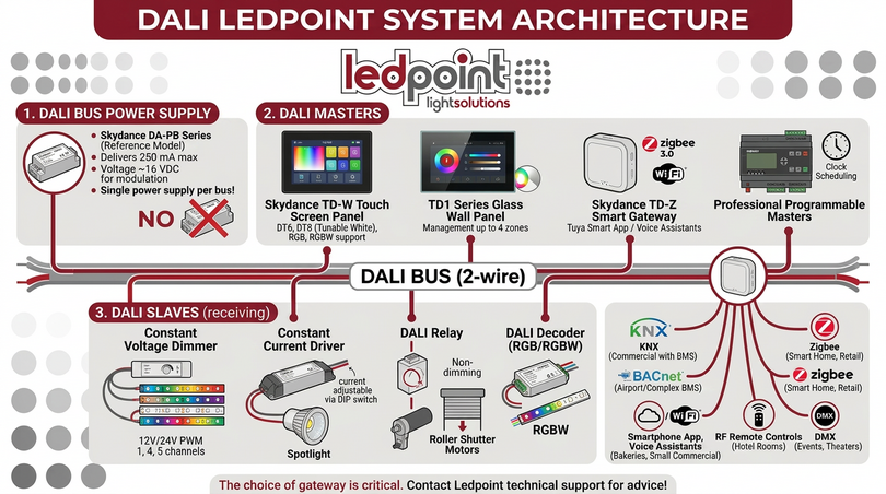
To correctly design a DALI system, it is essential to have a clear picture of the typical architecture of a system and the roles of the various components. A minimum DALI system is composed of four families of devices: the bus power supply, DALI masters, DALI slaves, and optionally DALI gateways to other protocols. In this chapter, we will look at each family, its functions, and the Ledpoint products available in the catalog.
The bus power supply: the power supply of the DALI system
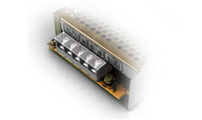
The first element of any DALI system is the bus power supply, i.e., the dedicated power supply for the DALI bus. Without a bus power supply, no DALI device can communicate, because the service voltage of about 16 VDC necessary for the modulation of digital commands is missing. The bus power supply is a separate device (or integrated in some more advanced masters) that delivers a maximum of 250 mA on the DALI bus, sufficient to power up to 64 standard devices. In the Ledpoint catalog, the reference DALI bus power supply is the Skydance DA-PB series, which delivers 250 mA stabilized with short-circuit protection and LED status signaling.
A fundamental rule: in a DALI system, there must be one and only one active bus power supply per bus. Connecting two DALI bus power supplies on the same bus generates electrical conflicts and can damage the connected devices. If a DALI system requires more power because it exceeds the 250 mA absorption (a rare case that occurs only with very energy-hungry sensors), the correct solution is to divide the system into two separate DALI buses, each with its own bus power supply, and make them communicate through a multi-bus DALI gateway.
DALI masters: who controls the DALI system
DALI masters are the devices that send commands on the bus. In the Ledpoint world, the most requested DALI masters belong to four main categories:
- DALI touch screen panels (e.g., Skydance TD-W): panels with 1.54" color LCD displays that allow the end client to select scenes, groups, and individual devices with an intuitive graphical interface. They support DT6 (standard dimming), DT8-TC (dynamic white), RGB, RGBW, and RGB+CCT light types.
- TD series glass wall panels (e.g., Skydance TD1, TD2, TD3, TD4, TD5): ultra-sensitive tempered glass touch panels that manage up to 4 DALI addresses or independent zones via linear touch slides and color wheels.
- Smart DALI gateways (e.g., Skydance TD-Z, TD-W2): integrate Zigbee 3.0 or WiFi with the DALI bus, allowing control of the entire DALI system via the Tuya Smart app or via voice assistants like Amazon Alexa and Google Home. They act as a bridge between the cloud and the physical bus.
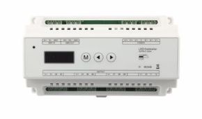
- Professional programmable masters: industrial controllers with customizable logic, time scheduling, management of multiple sensors, and integration with external BMS. Typical of congress centers, large hotels, and tertiary buildings.
DALI slaves: who executes the DALI system commands
DALI slaves are the devices that receive commands and translate them into actual variations on the light output. In the Ledpoint catalog, the most common DALI slaves are:
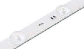
- Constant voltage DALI dimmers for LED strips: manage 12 V or 24 V LED strips with digital PWM dimming, in 1, 4, or 5 channel versions.
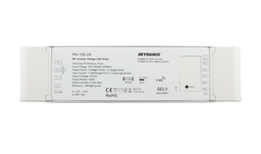
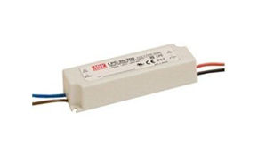
- Constant current DALI drivers: power professional LED spotlights and panels with current adjustable via DIP switch (e.g., 150 mA, 350 mA, 500 mA, 700 mA, 1050 mA, 1200 mA).
- DALI relays: switch non-dimmable loads (shutter motors, sockets, fans) following the DALI bus commands as if they were lighting fixtures.
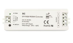
- DALI decoders for RGB/RGBW: translate DT8 commands from the DALI bus into PWM signals for multi-color LED strips.
DALI gateways: the DALI system talks to the rest of the world
DALI gateways are devices that put the DALI bus in communication with other protocols or networks. The most common DALI gateways are:
| DALI gateway type | What it does | Typical application |
|---|---|---|
| DALI ↔ KNX | Exposes DALI devices as KNX objects | Tertiary buildings with KNX BMS |
| DALI ↔ BACnet | Exposes DALI devices as BACnet/IP objects | BMS of complex buildings (hospitals, airports) |
| DALI ↔ Zigbee | Allows control of the DALI bus via Zigbee 3.0 | Smart home, retail, residential hospitality |
| DALI ↔ WiFi/Cloud | Control via smartphone app and voice assistants | Pastry shops, restaurants, B&Bs, small tertiary |
| DALI ↔ RF 2.4 GHz | RF remote controls can command the DALI bus | Hotel rooms, retrofit without apps |
| DALI ↔ DMX | DALI devices receive DMX commands or vice versa | Events, theaters, dynamic architectural lighting |
Choosing the correct DALI gateway is a critical design step that deserves dedicated technical consultancy: contact our technical support to receive a personalized principle diagram for your project.
5. DALI wiring diagrams: how to connect the system step by step
DALI wiring diagrams are one of the most searched topics online by installers and designers, because the DALI system, although conceptually simple, has some precise wiring rules that must be known to avoid operating problems. In this chapter, we present the typical diagrams of a modern DALI system and the practical laying rules to get the most out of the DALI system.
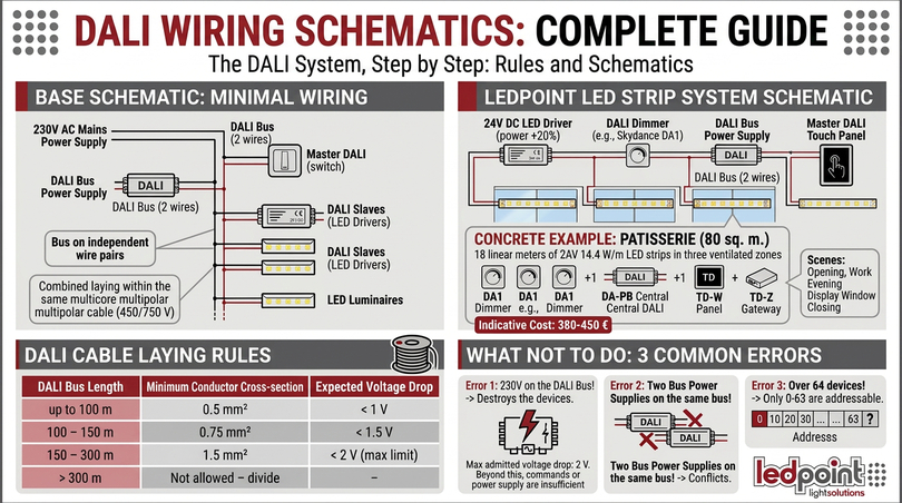
Basic DALI system diagram: the minimum wiring
The basic diagram of a DALI system includes these elements: 230 V AC mains power that powers the LED power supplies and the DALI bus power supply, the two-wire DALI bus that connects the bus power supply, DALI masters, and DALI slaves, and the output conductors of the power supplies that power the lighting fixtures (LEDs, LED strips, spotlights). The DALI bus travels on an independent pair of wires from the mains power, but can be laid in the same 450/750 V multipolar cable: this is one of the most appreciated features of the DALI system on construction sites, because it allows pulling a single cable from the junction box to the fixture.
DALI system diagram with Ledpoint LED strips
For a DALI system dedicated to the control of LED strips, one of the most frequent scenarios in residential projects and small tertiary, the typical diagram is as follows:
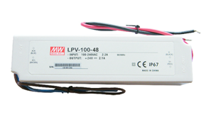
- 24 V DC LED power supply: physically powers the LED strip. It must be chosen with a power 20% higher than the maximum load to guarantee a safety margin.
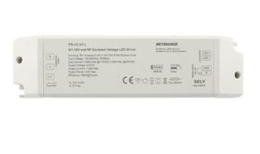
- Constant voltage DALI dimmer (e.g., Skydance DA1 for single channel, DA4 for RGBW, DA5-L for RGB+CCT): is inserted between the 24 V power supply and the LED strip, receives commands from the DALI bus, and digitally modulates in PWM the output to the LEDs.
- Two-wire DALI bus that connects the dimmer to the DALI master (touch panel, gateway, etc.).
- DALI bus power supply connected to the bus, generally in a central position of the system to minimize voltage drops.
- DALI master (touch panel, WiFi/Zigbee gateway) connected to the DALI bus.
Concrete numerical example: an 80 m² pastry shop with 18 linear meters of LED strips 24 V 14.4 W/m divided into three zones (showcase, counter, room). The optimal DALI system for this project provides three Skydance DA1 constant voltage DALI dimmers (one per zone), a centralized DA-PB bus power supply, a TD-W touch panel for manual management, and a TD-Z gateway for integration with the Tuya app and Alexa. Indicative cost of DALI components: 380-450 €; operational advantage: "opening", "work", "evening showcase display", and "closing" scenes recallable with a touch.
DALI cable laying rules: length, cross-section, voltage drop
The design of the DALI bus cable follows three practical rules that are fundamental to respect to guarantee the correct functioning of the DALI system:
| DALI bus length | Minimum conductor cross-section | Expected voltage drop |
|---|---|---|
| up to 100 m | 0.5 mm² | < 1 V |
| 100 – 150 m | 0.75 mm² | < 1.5 V |
| 150 – 300 m | 1.5 mm² | < 2 V (max limit) |
| > 300 m | Not allowed – divide into multiple DALI buses | – |
The maximum allowed voltage drop between the DALI bus power supply and the furthest device is 2 V. Exceeding this threshold means that some DALI devices might not receive commands correctly or, worse, not be powered sufficiently to respond to the master. For large DALI systems, the practical rule is: position the DALI bus power supply centrally with respect to the load of slaves and, if necessary, divide the bus into multiple parallel sections.
What NOT to do in DALI system wiring
Three classic mistakes we regularly see on construction sites when working with the DALI system:
- Mistake 1: using the DALI bus conductors as a 230 V "pilot wire". The DALI bus works at 16 VDC and cannot withstand mains voltages: sending 230 V to the DALI bus instantly destroys all connected devices.
- Mistake 2: connecting two DALI bus power supplies on the same bus. It generates conflicts that prevent communication and can damage the power supplies.
- Mistake 3: exceeding 64 devices on the same DALI bus. Even if it sometimes seems to work, DALI addressing is limited to 0-63 and devices beyond the 64th are not recognized by the master.
6. DALI system with LED strips: Ledpoint dimmers, drivers, decoders
The combination of the DALI system and LED strips is one of the most frequent application scenarios in contemporary lighting projects, both residential and professional. Ledpoint LED strips, managed via dedicated DALI dimmers, offer unmatched design flexibility: fluid dimming, color control, memorizable scenes, home automation integration. Let's see the key products and typical scenarios.
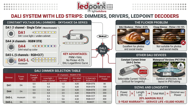
Constant voltage DALI dimmers for 12V and 24V LED strips
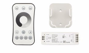
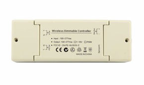
The constant voltage DALI dimmers of the Skydance DA series distributed by Ledpoint are specifically designed to drive 12 V or 24 V DC LED strips. They are available in three main configurations:
- DALI Dimmer DA1 (1 channel): for monochromatic LED strips, manages a single PWM channel with max power up to 240 W at 24 V. Ideal for diffused white lighting, cove light, under-cabinet kitchen, plasterboard false ceilings.
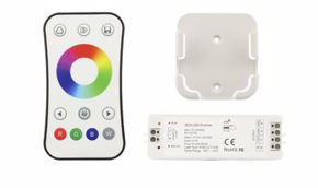
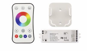
- DALI Dimmer DA4 (4 channels): for RGBW LED strips, manages four independent channels to control RGB color plus white. Compatible with device type 8 (DT8) of DALI-2 for color management via xy chromaticity.
- DALI Dimmer DA5-L (5 channels): for RGB+CCT LED strips (RGB + cool white + warm white), manages five channels for maximum chromatic flexibility. Used in showrooms, premium retail, museum environments.
All DALI dimmers of the DA series use high-frequency digital PWM dimming (over 1 kHz) with a logarithmic curve compliant with the DALI standard, completely eliminating perceptible flicker and unwanted flicker. This is a critical point for environments like pastry shops, retail showcases, and photo sets, where the flicker of LED strips can ruin photos of products taken by clients and published on social media: the Skydance DALI system guarantees a flicker percentage of less than 0.5%, while cheap analog dimmers often stand at over 10-15%.
Constant current DALI drivers for spotlights and panels
For lighting fixtures that are not LED strips but spotlights, LED panels, downlights, or professional linear profiles, the DALI system uses constant current drivers. In the Ledpoint catalog, the most common constant current DALI drivers are of the Skydance DA4-C series, which allow selecting the output current (150, 250, 350, 500, 700, 900, 1200 mA) via physical DIP switches, guaranteeing compatibility with a huge variety of LED sources. Selecting the correct current is critical: a current too high reduces the useful life of the LED, a current too low reduces the luminous flux.
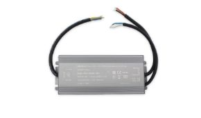
Waterproof DALI versions for outdoor installations
For outdoor applications (architectural facades, lateral lighting of historical buildings, radial lighting of squares, lighting of external showcases, perimeter lighting of gardens)— waterproof versions of the DALI system with IP67 and IP68 protection degrees are available. Models like the Skydance DA4-WPS offer IP67 protection with a sealed die-cast enclosure, resistant to temporary immersion and direct water jets. The DALI bus in outdoor installations must be laid in IP65 conduit minimum and connectors must be chosen with a protection degree consistent with the environment.
Selection table for Ledpoint LED strip DALI dimmers
| LED strip type | Voltage | Recommended DALI dimmer | Max power |
|---|---|---|---|
| Monochromatic LED strip | 24 V DC | Skydance DA1 | 240 W |
| Dynamic white LED strip (CCT) | 24 V DC | Skydance DA2 (2 channels) | 192 W |
| RGB LED strip | 24 V DC | Skydance DA3 (3 channels) | 288 W |
| RGBW LED strip | 24 V DC | Skydance DA4 | 384 W |
| RGB+CCT LED strip | 24 V DC | Skydance DA5-L | 480 W |
| Outdoor IP67 LED strip | 24 V DC | Skydance DA4-WPS | 384 W IP67 |
To correctly size the DALI dimmer, it is sufficient to multiply the power per meter of the LED strip (in W/m) by the total length (in meters) and verify that the result is lower than the maximum power of the dimmer. A practical rule: always leave a 20% margin on the nominal power of the DALI dimmer to avoid overheating and to guarantee the longevity of the component. All Skydance DALI dimmers distributed by Ledpoint are guaranteed for 5 years and declare an average useful life of over 50,000 hours of continuous operation.
7. Skydance DALI ecosystem: controllers, panels, Tuya/Zigbee gateways
Within a modern DALI system, the Skydance ecosystem distributed by Ledpoint is positioned as a complete and versatile solution, offering devices that cover every need: from central control (Master) to power regulation (Dimmer/Driver), up to integration with other protocols such as Zigbee, WiFi, Bluetooth, and RF 2.4 GHz. Skydance is today one of the few manufacturers in the world that offers a complete catalog of DALI-2 compatible products at accessible prices, maintaining professional-level quality standards and international certifications (CE, RoHS, FCC, ENEC). Ledpoint has been the official Skydance distributor for the Italian market since 2021 and keeps all the most requested references in stock with delivery in 24-48 hours.
Skydance DALI Masters: the brain of the DALI system
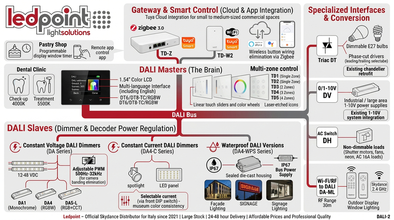
Skydance DALI Masters are the main control devices that send commands along the bus to all connected components. Skydance offers different types of DALI masters, each designed for a specific application context: flush-mounted touch panels for hotel rooms and executive offices, thin wall panels for retail environments, smart gateways for home automation integration, scene controllers for conference rooms.
DALI touch screen panels (e.g., Skydance TD-W)
Skydance TD-W series touch screen panels are equipped with 1.54-inch color LCD screens that allow intuitive configuration of DALI addresses, DALI groups, and DALI scenes directly from the display, without the need for external software. They support the control of different light types: standard dimming (DT6 of DALI), dynamic white (DT8-TC for color temperature control), RGB, RGBW, and RGB+CCT, covering practically all LED sources on the market. The graphical interface of the TD-W DALI panel is in Italian, English, French, German, Spanish, and Chinese, and is structured in three levels: home with favorite scenes, single group control, single DALI device control.
Typical use case for a TD-W DALI touch panel: 200 m² dental clinic with four operating rooms, waiting room, reception, and corridor. The TD-W DALI touch panel installed in reception allows staff to recall with a touch the scenarios "opening" (full light everywhere), "operative" (full light in rooms, dimmed in reception), "closing" (security only) and to manually adjust the color temperature of the operating rooms from 4000 K (clinical visit) to 5500 K (dental procedure) to optimize the dentist's vision during the most complex procedures.
TD series wall panels (Skydance TD1-TD5)
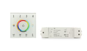
Skydance TD1, TD2, TD3, TD4, TD5 series wall panels are ultra-sensitive tempered glass panels that allow managing up to 4 DALI addresses or independent DALI zones via linear touch slides and color wheels. They are designed for applications where the aesthetics of the control are an integral part of the architectural project: the black or white glass with laser-engraved icons integrates perfectly into contemporary and minimalist environments, worthily replacing traditional lever switches or mechanical buttons. The TD1 and TD2 models offer single-zone commands, while TD3, TD4, and TD5 manage 2, 3, and 4 independent DALI zones respectively, with the possibility of scenes for each zone.
Smart DALI gateways (Skydance TD-Z, TD-W2)
Skydance smart DALI gateways integrate the Zigbee 3.0 protocol (TD-Z model) or WiFi (TD-W2 model) with the DALI system. This allows managing the entire DALI system via the Tuya Smart app or voice assistants like Amazon Alexa and Google Home, acting as a bridge between the cloud and the physical DALI bus. The TD-Z DALI gateway, in particular, is today one of the preferred choices by Ledpoint for small-medium tertiary projects because it combines the reliability of the wired DALI bus with the flexibility of wireless control via Zigbee, eliminating the need to lay additional cables for smart buttons or additional sensors.
Real Ledpoint use case: historic pastry shop in the center of Bologna, 65 m² on two levels, lighting composed of 22 meters of LED strips, 8 point spotlights above the counter, and 4 decorative suspensions. The implemented DALI system provides a Skydance TD-Z gateway that exposes the entire system on the Tuya Smart app, allowing the owner to turn on/off and adjust the lighting even from home in the evening, to program switching times (evening showcase on until midnight, security light all night), and to recall specific scenes for special occasions (birthdays, themed cake exhibitions, evening events). Total cost of the DALI system: 1,250 € out of 18,000 € total for the lighting project, i.e., less than 7% of the budget.
Skydance DALI Dimmers and Decoders (Slave Devices)
These devices receive signals from the Master and directly regulate the energy sent to the LEDs. The Skydance range covers the most diverse needs with three main families of DALI slaves.
Constant voltage DALI dimmers (DA series)
Skydance DA series DALI dimmers are specifically designed for constant voltage LED strips and are available in 1-channel versions (DA1 for monochromatic LEDs), 4 channels (DA4 for RGBW), or 5 channels (DA5-L for RGB+CCT). They operate at 12-48 VDC and use digital PWM dimming with a logarithmic curve compliant with DALI standards, guaranteeing fluid transitions, absence of flicker, and perfect perceptual linearity over the entire dimming scale. The working PWM frequency is adjustable via software between 500 Hz and 32 kHz: for applications where cameras or smartphones taking photos are present (shops, pastry shops, restaurants, event locations), Ledpoint recommends frequencies above 4 kHz to completely eliminate the banding effect.
Constant current DALI dimmers (DA4-C series)
Skydance DA4-C series constant current DALI dimmers are ideal for professional LED spotlights and panels. They allow selecting the output current (e.g., 150 mA, 250 mA, 350 mA, 500 mA, 700 mA, 900 mA, 1050 mA, 1200 mA) via front DIP switch, making the same device compatible with a huge variety of LED sources. They are particularly appreciated in museum projects and art galleries, where the LED driving current must be precisely controlled to guarantee chromatic consistency between different fixtures installed in the same environment.
Waterproof DALI versions (e.g., DA4-WPS)
For outdoor installations, models like the DA4-WPS Skydance offer IP67 protection with a sealed die-cast enclosure, resistant to dust, water jets, and temporary immersion up to 1 meter for 30 minutes. They are indispensable for architectural facade lighting, lateral lighting of historical buildings, perimeter lighting of squares, radial lighting of road roundabouts, lighting of external showcases of pastry shops and restaurants, lighting of advertising luminous signs. The Skydance waterproof range also includes DALI bus power supplies in IP67 version, indispensable for entirely outdoor DALI systems.
Conversion and specialized interfaces of the Skydance DALI system
The strength of the Skydance ecosystem lies in its ability to make the DALI system dialogue with other technologies and with light sources not natively DALI. Skydance produces various specialized interfaces that enormously expand the application perimeter of the DALI system:
DALI Triac Dimmer (DT series)
They allow inserting dimmable LED bulbs or phase-cut drivers (Triac/MOSFET) into the DALI system. They support both leading-edge dimming (cut on the rising edge, typical of old halogen lamps) and trailing-edge (cut on the falling edge, optimal for LEDs) and are selectable via DIP switch. Typical application: renovation of an apartment where you want to keep existing chandeliers with dimmable E27 LED bulbs, but you want to manage the entire system with a modern DALI master. The DALI Triac Dimmer DT is inserted between the DALI bus and the existing dimmable bulb.
DALI 0/1-10V Dimmer (DV series)
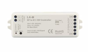
They convert the digital signal of the DALI bus into an analog 0-10V or 1-10V signal to control dimmable power supplies of older generations or of large powers, typical of industrial lighting and sheds. They are fundamental in retrofit projects, where you want to bring the old existing 1-10V system into the era of the modern DALI system without having to replace all the power supplies. The Skydance DV1 and DV4 DALI ↔ 0-10V converters are the most requested models.
DALI AC Switch (DH series)
They work as relays to turn on or off non-dimmable loads via the DALI bus, such as shutter motors, sockets, fans, neon lights, traditional non-LED light sources. They are devices that the DALI system sees as "lighting devices" but which actually switch any AC load up to 16 A: useful for centralizing the control of all the systems of an environment on a single DALI bus, even if only the lighting is actually dimmable.
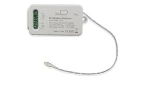
WiFi/RF to DALI converters (DA-ML series)
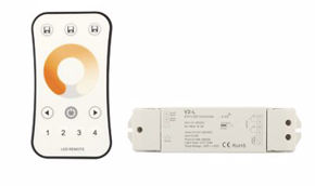
They allow using common 2.4 GHz Skydance RF remote controls to command devices on the DALI bus, making the system controllable even without wires and without apps, simply with a table or wall remote control. They are very requested in hotel rooms where you want to offer the client an intuitive remote control to manage ambient light and reading light, maintaining behind the scenes a DALI infrastructure manageable from the reception. The range of the Skydance RF remote control is about 30 meters in open spaces and 15 meters through standard walls.
Details on the technical operation of the Skydance DALI system
Skydance DALI addressing
Skydance DALI devices support automatic address assignment by the DALI Master, according to the standard DALI procedure of "random addressing" provided for by the IEC 62386 standard. In addition, many Skydance models also allow manual setting of the DALI address via digital display or front buttons, an option much appreciated by installers who prefer to assign addresses a priori, during wiring, rather than relying on automatic random addressing. This flexibility is particularly useful in very large DALI systems (50-64 devices on the same bus), where the random addressing procedure can take a few minutes and where an error in manual addressing is easily correctable on the single device.
Skydance DALI system dimming curves
By default, Skydance DALI dimmers use a logarithmic curve for dimming, since the human eye perceives brightness variations in a non-linear way and a logarithmic curve guarantees perceptually uniform variations. However, on advanced models, the curve is selectable between linear, logarithmic, and square (quadratic), an option useful in cinematic applications, in optical metrology laboratories, or in LED quality tests. The selected curve is stored in the non-volatile memory of the device and maintained even in case of power interruption.
Protocols supported by the Skydance DALI system
All Skydance devices distributed by Ledpoint comply with DALI-2 standards (IEC 62386), guaranteeing safe interoperability with products from other manufacturers on the same DALI bus. The most advanced devices simultaneously support DALI device types DT6 (standard dimming), DT8-TC (tunable white), DT8-RGB, DT8-RGBW, and DT8-XY, covering all modern lighting cases. For projects requiring official DALI-2 certification to participate in public tenders, Skydance provides DALI Alliance certificates downloadable from the official consortium website.
Power supply of the Skydance DALI bus
A DALI system always requires a dedicated bus power supply (e.g., Skydance DA-PL DIN rail or DA-PB compact) that delivers about 16 VDC stabilized to power the communication between devices on the DALI bus. The Skydance DA-PB bus power supply delivers 250 mA, sufficient to saturate an entire DALI bus with 64 devices at full load, and is equipped with short-circuit, overload, and polarity inversion protection. The front status LED signals correct operation and the presence of anomalies on the bus, greatly simplifying diagnostics during the commissioning phase of the DALI system.
In summary: what makes the Skydance DALI ecosystem special
In summary, Skydance controllers transform the DALI system into a flexible infrastructure, capable of integrating elegant touch commands, remote control via smartphone, and management of any LED light source, from the cheapest RGB LED strip to the high-end tunable white LED panel. The completeness of the range, certified compliance with the DALI-2 standard, the 5-year guarantee, and the competitive price make Skydance the natural choice for medium-range DALI system projects and for designers who want freedom to mix with other manufacturers without incurring interoperability problems.
8. DALI dimmers: how logarithmic digital dimming works
The DALI dimmer is one of the key components of any DALI system and deserves a dedicated deep dive, because the quality of DALI dimming is one of the main criteria for which designers choose the DALI system over other protocols. Understanding how a DALI dimmer works means understanding how the digital signal of the DALI bus is translated into an actual variation of the luminous flux emitted by the LED source. In this chapter, we address the four fundamental technical aspects of the DALI dimmer: the dimming curve, the PWM frequency, the fade time, and flicker management.
The logarithmic dimming curve of the DALI system
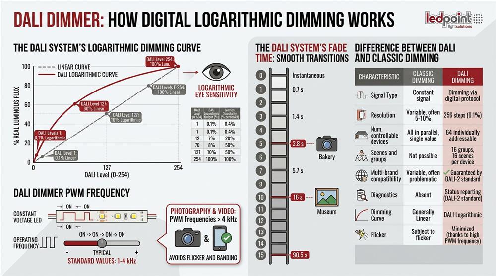
The dimming curve of the DALI system is logarithmic, and this is one of the main technical reasons why DALI dimming is perceived as more "natural" compared to a linear dimming of equal resolution. The human eye has a logarithmic sensitivity to brightness variations: this means that the perceived difference between 10% and 20% brightness is similar to the perceived difference between 50% and 100%, even if in absolute terms of luminous flux the second interval is five times wider than the first. A linear dimming curve, therefore, would produce "non-uniform" variations in perception: at low levels, the variations would be very evident, at high levels almost imperceptible.
The DALI system solves this critical issue by adopting a logarithmic dimming curve by default, in which DALI level 1 corresponds to 0.1% of real luminous flux, DALI level 254 corresponds to 100%, and all intermediate levels follow a logarithmic progression calculated according to the standardized DALI formula. This curve ensures that pressing "+1" on the DALI dimmer produces a perceived uniform variation over the entire scale, making the use of the DALI dimmer much more pleasant and professional compared to a common analog dimmer.
| DALI Level | % real luminous flux (log curve) | % real luminous flux (linear curve) |
|---|---|---|
| 0 | OFF | OFF |
| 1 | 0.1% | 0.4% |
| 32 | 0.5% | 12.6% |
| 85 | 3.2% | 33.5% |
| 127 | 10% | 50% |
| 170 | 26.5% | 67% |
| 212 | 56% | 83.5% |
| 254 | 100% | 100% |
This table shows the difference between the DALI logarithmic curve and the linear curve: the standard DALI curve allows appreciating significant variations even at low levels (important for environments like restaurants, conference rooms, bedrooms, museum environments where light is often used at reduced levels), while the linear curve "compresses" all the nuances of low levels into a few initial steps.
The PWM frequency of DALI dimmers
Constant voltage DALI dimmers regulate the brightness of LED strips via PWM (Pulse Width Modulation): in practice, they turn the power of the LED strip on and off very quickly, and the percentage of time the strip is "on" compared to the total cycle determines the perceived brightness. The PWM frequency is how quickly this on/off cycle occurs, and in modern DALI dimmers it typically ranges between 500 Hz and 32 kHz, with default values around 1-4 kHz.
Why is the PWM frequency important? Because frequencies too low (below 200 Hz) are perceived by the human eye as "flicker", and frequencies below 2-3 kHz can create problems with surveillance cameras (banding effect on images) and with photos taken by smartphones (visible horizontal stripes). For environments where the aesthetics of images matter (pastry shops with clients photographing products, retail showcases, photo sets, event locations, TV studios) Ledpoint recommends setting Skydance DALI dimmers to PWM frequencies above 4 kHz, a threshold beyond which even professional cameras and the most sensitive smartphones no longer detect any banding.
The fade time of the DALI system: smooth transitions
The fade time is the time the DALI dimmer takes to pass from one brightness level to another. The DALI system provides 16 standardized fade times, from 0 seconds (instant change) up to 90.5 seconds, calculated according to an exponential progression. The fade time is a very powerful design tool: a 4-second transition between two scenes makes the environment "alive" and pleasant, while an instant change is perceived as abrupt and unprofessional.
| DALI fade time | Duration (seconds) | Typical application |
|---|---|---|
| 0 | Instant | Emergency, security, bathroom on |
| 1 | 0.7 s | Normal button, standard on |
| 3 | 1.4 s | Bedroom, living room |
| 5 | 2.8 s | Pastry shop, retail, restaurant |
| 7 | 5.7 s | Conference room, scene transition |
| 10 | 16 s | Museum, gallery, slow transition |
| 15 | 90.5 s | Simulated sunrise/sunset, kindergartens |
Difference between DALI and classic dimming
A recurring question is: what is the difference between DALI and classic dimming? Classic dimming (Triac, phase cut, 0-10V, 1-10V) is an analog regulation of the voltage or current that directly powers the light source, while DALI dimming is a digital command that the LED driver executes internally by generating its PWM or its regulated current.
| Feature | Classic dimming | DALI dimming |
|---|---|---|
| Signal type | Analog (voltage, phase cut) | Digital (DALI bus) |
| Resolution | Variable, often 5-10% | 256 levels (precision <0.4%) |
| Number of controllable fixtures | All in parallel, same value | 64 individually addressable |
| Scenes and groups | Not possible | 16 groups, 16 scenes per device |
| Multi-brand compatibility | Variable, often problematic | Guaranteed by DALI-2 standard |
| Diagnostics | Absent | Status reporting in DALI-2 |
| Dimming curve | Typically linear | Logarithmic (natural perception) |
| Flicker | Often problematic (high % flicker) | < 0.5% in certified products |
The conclusion is clear: for any modern professional system with more than 4-5 dimmable lighting fixtures, the DALI system is technically superior to analog dimming in all relevant aspects, with an initial surcharge of 15-25% that is amortized in the medium term by greater flexibility, lower maintenance, and a better end-user experience.
9. DALI power supplies: selection, sizing, bus power supply
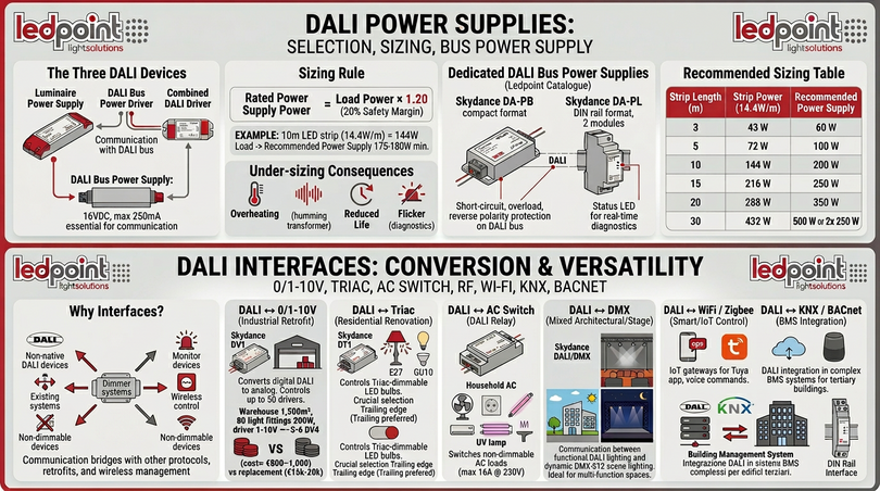
The choice of the correct DALI power supply is one of the most delicate steps in the design of a DALI system, because it involves three distinct devices that are often confused with each other: the mains power supply of the lighting fixture, the DALI bus power supply, and any DALI driver that does both functions. In this chapter, we definitively clarify the terminology and provide the sizing criteria used daily by Ledpoint in its DALI projects.
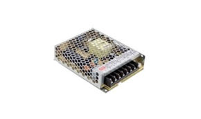
The lighting fixture power supply
The lighting fixture power supply is the device that converts the 230 V AC mains voltage into the voltage or current required by the LED (12 V DC, 24 V DC, 36 V DC, 48 V DC for LED strips, or typical currents 350-1200 mA for constant current LEDs). This power supply can be "DALI" (i.e., with integrated DALI bus input) or "non-DALI" (i.e., with standard 12/24 V DC output which is then modulated by a separate DALI dimmer). The choice between the two options depends on the architecture of the project: for LED strips, the "non-DALI" power supply + separate Skydance DALI dimmer is almost always convenient (more flexible and less expensive), while for spotlights and LED panels, the integrated DALI power supply may be convenient.
The DALI bus power supply
The DALI bus power supply is the dedicated power supply for the DALI communication bus. It delivers about 16 VDC stabilized to a maximum of 250 mA and is indispensable for any DALI system. Without a DALI bus power supply, no device on the bus can communicate, because the service voltage necessary for the DALI protocol is missing. In small DALI systems (up to 10-15 devices), the DALI bus power supply can be integrated into the gateway or the most advanced master; in medium and large DALI systems, it is appropriate to use a dedicated DALI bus power supply, positioned centrally with respect to the load.
How to size the DALI power supply of the lighting fixture
The practical rule for sizing the DALI power supply of the lighting fixture is as follows: nominal power of the power supply = total power of the LED load × 1.20 (20% safety margin). Example: 10 meters of LED strip at 14.4 W/m = 144 W of load → recommended power supply 175-180 W minimum. Under-sizing the DALI power supply means making it work constantly at the limit, with consequent overheating, acoustic noise (transformer hum), drastic reduction of useful life, and visible flicker on the LED strip.
| LED strip length | Strip power (14.4 W/m) | Recommended power supply |
|---|---|---|
| 3 m | 43 W | 60 W |
| 5 m | 72 W | 100 W |
| 10 m | 144 W | 200 W |
| 15 m | 216 W | 250 W |
| 20 m | 288 W | 350 W |
| 30 m | 432 W | 500 W (or 2× 250 W) |
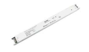
Skydance DA-PB and DA-PL DALI bus power supplies
In the Ledpoint catalog, the reference DALI bus power supplies are the Skydance DA-PB (compact format, flush-mounted or for electrical panel, delivers 100-250 mA selectable) and the Skydance DA-PL (DIN rail format, 2 modules, delivers 250 mA, ideal for tertiary and industrial electrical panels). Both models are equipped with short-circuit, overload, and polarity inversion protection on the DALI bus, and a front status LED that signals in real time the correct operation of the bus and any presence of anomalies. Immediate visual diagnostics is a great help during the commissioning phase of the DALI system and in case of maintenance interventions.
10. DALI interfaces: 0/1-10V, Triac, AC Switch, RF, WiFi
One of the features that make the DALI system extremely versatile in the design phase is the availability of conversion interfaces between DALI and other protocols or technologies. These interfaces allow the DALI system to dialogue with non-natively DALI devices, to integrate into existing systems, to manage non-dimmable loads, and to be controlled wirelessly. In this chapter, we review all the most important DALI interfaces and their application scenarios.
DALI ↔ 0-10V and 1-10V interface
The DALI ↔ 0-10V (or 1-10V) interface converts the digital signal of the DALI bus into an analog 0-10V or 1-10V signal, and vice versa. This DALI interface is fundamental in retrofit projects, where 0-10V or 1-10V power supplies are already installed and you want to bring the system into the era of the DALI system without having to replace all the drivers. The typical DALI ↔ 0-10V interface is the Skydance DV1 (1 channel) or DV4 (4 channels), with analog output from 0 to 10 V (internal resistance selectable to sourcing or sinking) capable of driving up to 50 0-10V drivers in parallel.
Typical scenario: a 1,500 m² industrial shed with 80 200 W industrial LED ceiling lights equipped with 1-10V dimmable drivers installed in 2018. To bring the system to the modern DALI system with scenes, groups, presence sensors, and control via app, you can insert 5-6 Skydance DV4 DALI ↔ 0-10V interfaces in the existing electrical panels, keeping drivers, ceiling lights, and wiring intact, with a DALI update cost of about 800-1,000 € plus the programming of the masters, against the 15,000-20,000 € that would be needed to replace the 80 drivers.
DALI ↔ Triac interface (phase cut)
The DALI ↔ Triac interface converts the digital signal of the DALI bus into an analog phase cut, leading-edge or trailing-edge, to drive dimmable E27/E14/GU10 LED bulbs dimmable by Triac. This DALI interface is indispensable in high-level residential renovation projects, where you want to maintain the aesthetic value of existing chandeliers and decorative lamps, but you want to bring the entire lighting management under the control of the centralized DALI system.
Typical Skydance models: DT1 (1 channel, max 300 W load) and DT2 (2 channels). The selection between leading-edge and trailing-edge dimming is fundamental: modern dimmable LEDs prefer trailing-edge (cut on the falling edge) because it generates less interference on the internal LED power supply and reduces flicker.
DALI ↔ AC Switch interface
The DALI ↔ AC Switch interface (DALI relay) simply switches non-dimmable AC loads (maximum 16 A at 230 V) receiving commands from the DALI bus as if it were a normal lighting fixture. It allows centralizing in the DALI system the control of devices that are not dimmable: electric shutter motors, fans, service sockets, non-dimmable neon lights, halogen lamps with traditional transformers, UV sources for sterilization.
DALI ↔ DMX interface
The DALI ↔ DMX interface converts DALI commands into DMX-512 (and vice versa), allowing two different ecosystems to dialogue: DALI, typical of tertiary architectural lighting, and DMX, typical of scenic, theatrical, and event lighting. This DALI interface is precious in mixed projects such as multi-function venues, congress centers with evening use for musical events, restaurants with live animation, lounge bars: DALI manages the functional light during the day, DMX manages the dynamic effects in the evening, and the interface allows passing from one mode to the other without reconfigurations.
DALI ↔ WiFi and Zigbee interface (wireless control)
The DALI ↔ WiFi interface (e.g., Skydance TD-W2) and the DALI ↔ Zigbee 3.0 interface (e.g., Skydance TD-Z) are the entry doors of the DALI system into the IoT and smart home universe. These DALI interfaces expose the DALI bus on the Tuya Smart app (compatible with Alexa, Google Home, Siri Shortcuts) or on standard Zigbee gateways, allowing control via smartphone, tablet, voice commands, and smart home routines. They are today one of the preferred choices of Ledpoint for small tertiary and evolved residential projects, where the flexibility of wired DALI merges with the user experience of the smart device.
DALI ↔ KNX and BACnet interface
In projects of complex tertiary buildings with BMS (Building Management System) based on KNX or BACnet, the DALI ↔ KNX and DALI ↔ BACnet interface exposes the DALI bus as native objects of the building's bus protocol. It allows the central BMS to manage DALI lighting together with climate, security, intrusion detection, access control, and energy management. Typically, these DALI interfaces are professional DIN rail devices with a double bus (DALI on one side, KNX/BACnet on the other) and configuration via ETS tool or proprietary software.
11. Applications of the DALI system: pastry shops, congress centers, retail, museums, buses
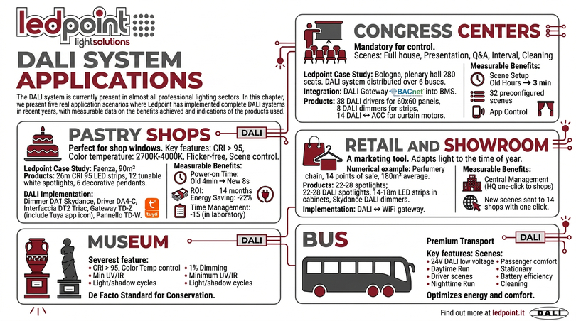
The DALI system is today present in almost all sectors of professional lighting. In this chapter, we present five real application scenarios in which Ledpoint has implemented complete DALI systems in recent years, with measurable data on the benefits obtained and indications on the products used.
DALI system for pastry shops: perfect lighting for the showcase
Pastry shops are one of the sectors where the DALI system offers the most tangible advantages. A well-designed LED lighting system for pastry shops must guarantee CRI > 95 on the showcase (to enhance the natural colors of sweets), color temperature between 2700 K (warm, welcoming) and 4000 K (neutral, professional), zero flicker (for client photos), and differentiated scenes for the moments of the day (opening, work, display, closing).
Ledpoint case: historic pastry shop in Faenza, 90 m² on two levels, 26 linear meters of CRI 95 LED strips in the showcase and under the counter, 12 tunable white LED spotlights 2700-4000K above the counter, 6 dimmable decorative suspensions in the room. The implemented DALI system provides 4 Skydance DA1 DALI dimmers for the showcase strips, 2 DA4-C constant current DALI drivers for the spotlights, 1 DALI ↔ Triac DT2 interface for the suspensions, TD-Z gateway with Tuya app, and TD-W touch panel in the laboratory. Morning switching on times: from 4 minutes (old non-DALI system, manual switching on of 6 switches) to 8 seconds (DALI "opening" scene from touch panel). ROI of the DALI investment: estimated at 14 months thanks to energy saving (-22%) and reduction of management times (-15 min/day).
DALI system for congress centers and conference rooms
Lighting for congress centers is a scenario where the DALI system is practically mandatory: a modern conference room requires scenes of "full audience" (high uniform light), "presentation" (front light off or reduced, back on), "Q&A" (medium audience light, microphones highlighted), "break" (warm diffused light), "cleaning" (maximum light everywhere). Without a DALI system, it is simply impossible to manage these scenes in a reliable and repeatable way, and even more impossible to do it with a remote control in the hands of the moderator.
Ledpoint case: congress center in the province of Bologna, plenary hall 280 seats + 4 parallel rooms of 50 seats. DALI system distributed over 6 separate DALI buses with DALI ↔ BACnet gateway integrated into the building's BMS, 38 constant current DALI drivers for 60×60 LED panels, 8 DALI dimmers for perimeter decorative LED strips, 14 DALI ↔ AC Switch interfaces for blind motors. Average time to set up a new scene: 3 minutes from the touch panel in the control room, against the hours required by the old analog system. Availability of 32 preconfigured scenes recallable also via the organizer's app.
DALI system for retail and showrooms
In modern retail, lighting is a marketing tool as much as the arrangement of products. The DALI system allows the retail manager to adapt the light to the season, the time of day, the ongoing promotional campaign, without having to physically intervene on the system and without calling the electrician for every scene change. Clothing stores, jewelry stores, perfumeries, bookstores, contemporary concept stores massively use the DALI system for this reason.
Numerical example: chain of perfumeries in Emilia-Romagna, 14 points of sale of average surface 180 m², standardized system based on the DALI system. Each store has 22-28 CRI 95 constant current DALI LED spotlights, 14-18 meters of LED strips in display cabinets controlled by Skydance DALI dimmers, DALI ↔ WiFi gateway connected to the chain's central management system. Central marketing can send a new "DALI scene" to all 14 stores for the launch of a cosmetic line, activating it simultaneously throughout the network with a click from the central office.
DALI system for museum lighting
Museum lighting is the most severe testing ground for any lighting system: it requires CRI > 95, controlled color temperature, minimum UV/IR irradiation (for the conservation of works), precise dimming to the single percentage, possibility to program light/shadow cycles that simulate natural lighting. The DALI system is the de facto standard in modern museums because it combines all these needs in a single infrastructure manageable by the curator with a simple interface.
DALI system for buses and transport
A lesser-known but very interesting application of the DALI system concerns the lighting of buses, trains, and premium public transport means. The assembly of a lighting system on a modern bus provides for 24 V DC LED strips in the corridor ceilings, individual LED spotlights above each seat, lateral accent lighting, safety lighting with attenuated red light for night journeys. The DALI system in 24 V version (there are specific DALI low voltage adaptations for mobile means) allows the driver to manage "day driving", "night driving", "parking", "cleaning" scenes with a single command, optimizing passenger comfort and the energy efficiency of the vehicle's battery.
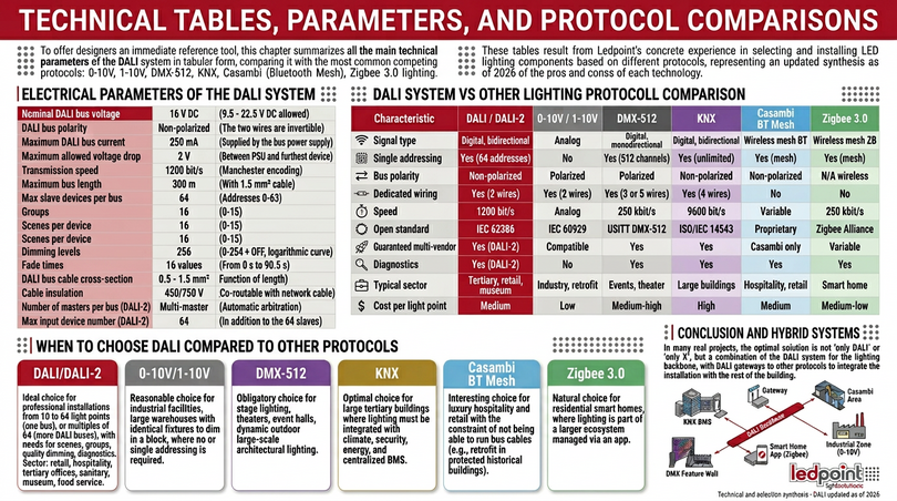
12. Technical tables, parameters, and comparisons between protocols
To offer designers an immediate reference tool, in this chapter we summarize in tabular form all the main technical parameters of the DALI system, comparing it with the most common competing protocols: 0-10V, 1-10V, DMX-512, KNX, Casambi (Bluetooth Mesh), Zigbee 3.0 lighting. These tables are the result of Ledpoint's concrete experience in selecting and installing LED lighting components based on the different protocols, and represent an updated synthesis for 2026 of the pros and cons of each technology.
Electrical parameters of the DALI system
| Parameter | Value | Tolerance/Notes |
|---|---|---|
| Nominal DALI bus voltage | 16 V DC | 9.5 – 22.5 V DC allowed |
| DALI bus polarity | Non-polarized | The two wires are reversible |
| Maximum DALI bus current | 250 mA | Delivered by the bus power supply |
| Maximum allowed voltage drop | 2 V | Between PSU and furthest device |
| Transmission speed | 1200 bit/s | Manchester encoding |
| Maximum bus length | 300 m | With 1.5 mm² cable |
| Max slave devices per bus | 64 | Addresses 0-63 |
| Groups | 16 | 0-15 |
| Scenes per device | 16 | 0-15 |
| Dimming levels | 256 | 0-254 + OFF, logarithmic curve |
| Fade times | 16 values | From 0 s to 90.5 s |
| DALI bus cable cross-section | 0.5 – 1.5 mm² | Function of length |
| Cable insulation | 450/750 V | Can be laid with power cable |
| Number of masters per bus (DALI-2) | Multi-master | Automatic arbitration |
| Max number of input devices (DALI-2) | 64 | In addition to the 64 slaves |
DALI system comparison vs other lighting protocols
| Feature | DALI / DALI-2 | 0-10V / 1-10V | DMX-512 | KNX | Casambi BT Mesh | Zigbee 3.0 |
|---|---|---|---|---|---|---|
| Signal type | Digital, bidirectional | Analog | Digital, unidirectional | Digital, bidirectional | Wireless mesh BT | Wireless mesh ZB |
| Single addressing | Yes (64 addresses) | No | Yes (512 channels) | Yes (unlimited) | Yes (mesh) | Yes (mesh) |
| Bus polarity | Non-polarized | Polarized | Polarized | Non-polarized | N/A wireless | N/A wireless |
| Dedicated wiring | Yes (2 wires) | Yes (2 wires) | Yes (3 or 5 wires) | Yes (4 wires) | No | No |
| Speed | 1200 bit/s | Analog | 250 kbit/s | 9600 bit/s | Variable | 250 kbit/s |
| Open standard | IEC 62386 | IEC 60929 | USITT DMX-512 | ISO/IEC 14543 | Proprietary | Zigbee Alliance |
| Multi-vendor guaranteed | Yes (DALI-2) | Compatible | Yes | Yes | Only Casambi | Variable |
| Diagnostics | Yes (DALI-2) | No | No | Yes | Yes | Yes |
| Typical sector | Tertiary, retail, museum | Industry, retrofit | Events, theater | Large buildings | Hospitality, retail | Smart home |
| Cost per light point | Medium | Low | Medium-high | High | Medium | Medium-low |
When to choose DALI over other protocols
The choice of the lighting protocol depends on concrete design factors: number of fixtures, scalability requirements, diagnostic requirements, budget, presence of an existing BMS, installation environment (indoor/outdoor, civil/industrial). Ledpoint's practical rule for orienting the choice between DALI and other protocols is as follows:
- DALI / DALI-2 system: ideal choice for professional systems from 10 to 64 light points (one bus), or multiples of 64 (multiple DALI buses), with a need for scenes, groups, quality dimming, diagnostics. Sector: retail, hospitality, tertiary offices, healthcare, museum, food service.
- 0-10V / 1-10V: reasonable choice for large industrial systems (sheds, warehouses) with all identical fixtures to be dimmed in bulk, where scenes or single addressing are not needed.
- DMX-512: mandatory choice for scenic lighting, theaters, event halls, large-scale dynamic external architectural lighting.
- KNX: optimal choice for large tertiary buildings where lighting must be integrated with climate, security, energy, and centralized BMS.
- Casambi (BT Mesh): interesting choice for luxury hospitality and retail with the constraint of not being able to lay bus cables (e.g., retrofit in protected historical buildings).
- Zigbee 3.0: natural choice for residential smart home, where lighting is part of a larger ecosystem managed via app.
In many real projects, the optimal solution is not "only DALI" or "only X", but a combination of the DALI system for the backbone of lighting, with DALI gateways to other protocols to integrate the system with the rest of the building. This hybrid architecture is exactly what Ledpoint proposes in complex projects.
13. DALI home automation and integration with KNX, Zigbee, WiFi, Bluetooth
DALI home automation is one of the fastest-growing areas of the market, because it combines the professional reliability of the wired DALI bus with the flexibility of use of modern smart home ecosystems. In this chapter, we see in detail how the DALI system integrates with the main home automation ecosystems available on the market: KNX, Zigbee 3.0, WiFi via Tuya/cloud, Bluetooth Mesh, Matter.
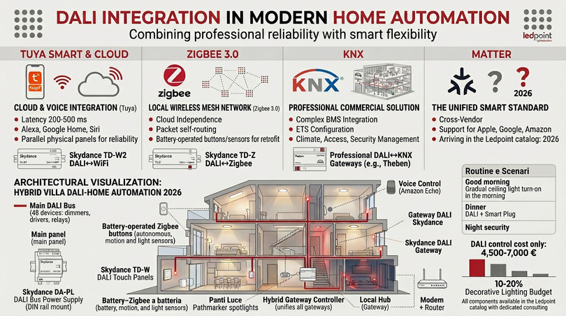
DALI home automation with Tuya Smart and voice assistants
The most widespread integration in evolved residential projects and small tertiary is between the DALI system and the Tuya cloud. Through a Skydance TD-W2 DALI ↔ WiFi gateway, the DALI bus is exposed on the Tuya Smart app, which natively manages Amazon Alexa, Google Home, Apple Siri Shortcuts, and Samsung SmartThings. This means that the DALI scenes configured on the bus can be recalled with a voice command ("Alexa, activate dinner scene"), via automatic routines based on time or presence, via widgets on the main screen of the smartphone, via integration with other smart home devices (e.g., the DALI light dims when the TV is turned on).
The typical latency of a DALI command conveyed via Tuya/WiFi is 200-500 ms, perfectly acceptable for daily use. To avoid dependence on the cloud (which requires an always-active internet connection), Ledpoint always recommends maintaining a physical control (touch panel or DALI keypad) in parallel that works independently of the WiFi gateway. In this way, if the internet connection drops, the DALI system continues to work without problems.
DALI home automation with Zigbee 3.0
The DALI ↔ Zigbee 3.0 integration via the Skydance TD-Z gateway is the preferred choice for projects where greater reliability than WiFi and independence from the cloud are desired. Zigbee 3.0 is a low-power wireless mesh protocol that operates at 2.4 GHz, with a typical range of 30-100 meters for each node and with the ability to auto-route packets through the nodes of the network, guaranteeing coverage even in complex buildings.
DALI ↔ Zigbee integration allows adding battery-powered Zigbee buttons to the wired DALI system (useful in retrofits where there is no cable), Zigbee presence/luminosity sensors, Zigbee remote controls, Zigbee smart plugs for the control of non-lighting loads, all integrated into a single app or coordinator. Zigbee hubs compatible with DALI: Tuya, Hue Bridge (with limitations), Home Assistant + Zigbee2MQTT, in addition to the native Skydance gateway.
DALI home automation with KNX
DALI ↔ KNX integration is the reference solution for large tertiary buildings where DALI lighting is one of many subsections of an overall KNX BMS that also manages climate, access, security, and energy. Professional DALI ↔ KNX gateways (e.g., Theben, MDT, ABB, Gira) expose each DALI device as a KNX object configurable via ETS (Engineering Tool Software), with all standard KNX functions (group objects, scenes, scheduling, logic).
Example: 6-story office building, 400 total rooms, centralized KNX BMS. Each floor has a dedicated DALI bus (4-5 total DALI buses) with 50-60 DALI devices each, connected to the KNX BMS via dedicated DALI ↔ KNX gateways. The KNX BMS then manages the complex logic (e.g., floor light on at 30% in "night security" mode, office light synchronized with the room booking system, common area light as a function of external weather via integrated weather station).
DALI home automation with Matter
Matter is the new cross-vendor smart home standard promoted by the Connectivity Standards Alliance (ex Zigbee Alliance) with the support of Apple, Google, Amazon, Samsung, and over 200 companies. Matter promises to unify smart home ecosystems, and DALI ↔ Matter gateways are appearing on the market starting in 2024. Ledpoint is carefully following the evolution of Matter and plans to integrate DALI ↔ Matter gateways into its catalog during 2026, as soon as the maturity of the ecosystem is such as to guarantee the stability necessary for professional systems.
Diagram of a hybrid domotic DALI system
To give a concrete idea of how a modern DALI system integrates into a home automation ecosystem, here is the typical architectural diagram of a high-level single-family villa realized by Ledpoint in 2025:
- Main DALI bus: 48 DALI devices including dimmers, drivers, and relays, distributed over three floors.
- DALI bus power supply: 1 Skydance DA-PL DIN rail in the main panel.
- DALI touch panels: 5 Skydance TD-W (one for each main zone: entrance, living room, kitchen, night area, terrace).
- DALI ↔ Zigbee 3.0 gateway: 1 Skydance TD-Z for integration with local Home Assistant.
- Battery-powered Zigbee buttons: 12 in points where it was not possible to lay cables.
- Zigbee sensors: 8 motion sensors + 3 luminosity sensors + 1 weather station.
- Voice control: 4 Amazon Echos distributed in the house.
- Smart routines: "Good morning" (gradual simulated sunrise light, 8 seconds fade), "Dinner" (DALI scene kitchen+living room dim 40% 2700K), "Night security" (red light placeholders in the corridors).
This type of hybrid DALI system represents the 2026 state of the art for luxury residences and evolved small tertiary, and all the components mentioned are available in the Ledpoint catalog with dedicated consultancy. The cost of the DALI control system alone in a system like the one described ranges between 4,500 and 7,000 € depending on the complexity, on a typical decorative lighting budget of 25,000-50,000 €, i.e., 10-20% of the total.
14. Costs, ROI, and market data of the DALI system in Italy
We now address a topic often avoided in technical articles but decisive for those who must choose whether to invest in a DALI system: real costs and return on investment. Below we report concrete and verifiable data on the average costs of a DALI system in Italy in 2026, divided by system type, and estimate the expected ROI as a function of the application sector.
Unit costs of DALI components
The indicative public prices of the main DALI components present in the Ledpoint catalog in 2026 are as follows (prices excluding VAT, subject to variation):
| DALI component | Skydance model | Indicative price |
|---|---|---|
| DALI bus power supply | DA-PB / DA-PL | 65 – 95 € |
| DALI dimmer 1 channel CV | DA1 | 52 – 68 € |
| DALI dimmer 4 channels CV RGBW | DA4 | 78 – 95 € |
| DALI dimmer 5 channels CV RGB+CCT | DA5-L | 95 – 115 € |
| DALI driver constant current | DA4-C | 88 – 110 € |
| DALI dimmer waterproof IP67 | DA4-WPS | 135 – 165 € |
| DALI touch panel | TD-W | 180 – 220 € |
| DALI wall panel 1 zone | TD1 | 95 – 120 € |
| DALI wall panel 4 zones | TD4 | 140 – 170 € |
| DALI ↔ Zigbee gateway | TD-Z | 165 – 195 € |
| DALI ↔ WiFi gateway | TD-W2 | 135 – 165 € |
| DALI ↔ Triac interface | DT1 / DT2 | 110 – 145 € |
| DALI ↔ 0-10V interface | DV1 / DV4 | 95 – 130 € |
| DALI relay AC Switch | DH1 / DH4 | 75 – 110 € |
| RF ↔ DALI converter | DA-ML | 85 – 120 € |
Average cost of a complete DALI system by type
| Environment type | Typical surface | DALI system - components only | DALI system with installation |
|---|---|---|---|
| Small pastry shop | 60-90 m² | 800 – 1,300 € | 1,500 – 2,500 € |
| Medium retail shop | 100-200 m² | 1,500 – 2,800 € | 2,800 – 5,000 € |
| Restaurant | 150-300 m² | 2,500 – 4,500 € | 4,500 – 8,500 € |
| Executive office | 200-400 m² | 3,500 – 6,500 € | 6,500 – 12,000 € |
| Conference room 80 seats | 120-180 m² | 2,800 – 5,000 € | 5,000 – 9,500 € |
| Large congress center | 500-1,500 m² | 12,000 – 35,000 € | 25,000 – 75,000 € |
| Luxury villa | 250-500 m² | 4,500 – 10,000 € | 8,500 – 20,000 € |
| Boutique hotel 30 rooms | 1,200-2,000 m² | 18,000 – 35,000 € | 40,000 – 85,000 € |
Expected ROI of the DALI system
The return on investment of a DALI system is not measured only in energy savings, but above all in value generated by the improved user experience and the reduction of operational times. Let's see four concrete cases analyzed by Ledpoint:
- Pastry shop: average energy saving 18-25%, reduction of on/off times 12 min/day, average increase in evening showcase turnover +6-12% (due to better display quality). Average ROI: 12-18 months.
- Office: energy saving 22-30% (thanks to DALI-2 presence sensors + daylight harvesting), improvement of employee well-being (dynamic CCT 3000-5000K). Average ROI: 18-30 months.
- Congress center: reduction of room setup times from 45 min to 5 min, possibility to rent the room 30% more times a year. Average ROI: 8-14 months.
- Hotel: reduction of corridor/common area consumption 35-45%, improvement of client review ratings for the quality of room lighting. Average ROI: 24-36 months.
2026 market data of the DALI system in Italy
To give an idea of the maturity of the Italian market for the DALI system, here are some data processed by Ledpoint based on its own orders, Light&Building sector research, and DALI Alliance 2024-2025 reports:
- Number of new DALI systems installed in Italy in 2025: estimated at over 28,000 units.
- DALI/DALI-2 share on total new professional lighting systems: 38% (Italy), 45% (Germany), 41% (France), 28% (Spain), 22% (UK).
- DALI-2 vs DALI v1 share in new purchases: 78% DALI-2, 22% DALI v1 (in constant decline).
- Sectoral distribution of DALI systems in Italy: 31% tertiary offices, 22% retail, 18% hospitality, 12% healthcare, 9% educational, 8% industrial.
- Average annual growth of the DALI market in Italy 2020-2025: +14.2% CAGR.
- Forecast 2026-2030: further growth 11-13% CAGR, driven by DALI-2 and home automation integration.
These numbers tell of a market in full maturity but still in strong growth, where the choice of the DALI system for a professional system is today the norm and no longer the exception. Investing in training and quality DALI components is the way to remain competitive in the Italian and European professional lighting market of the next 10-15 years.
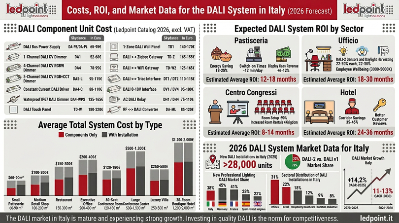
15. Common mistakes and best practices in DALI design
In Ledpoint's sixteen years of activity in the professional LED lighting sector, we have seen hundreds of well-designed DALI systems and as many, unfortunately, poorly designed or realized. In this concluding chapter before the FAQ, we collect the fifteen most common mistakes we see in the design and installation of a DALI system, and the corresponding best practices to avoid them. Knowing these mistakes before facing a DALI project will save you time, money, and frustrations, whether you are an installer new to the DALI system or an experienced designer who wants to compare yourself with an external point of view.
The fifteen most common DALI system mistakes
- Mixing DALI v1 and DALI-2 without planning: technically it is allowed, but the advanced functions of DALI-2 are lost. Best practice: in new systems, adopt only certified DALI-2 devices.
- Under-sizing the DALI bus power supply: with more than 30-40 devices on the bus, the risk of exceeding 250 mA is concrete. Best practice: calculate the total load of the DALI bus and size the PSU with a 20% margin.
- Exceeding 300 m of DALI bus length: beyond this threshold, the voltage drop generates communication problems. Best practice: divide into multiple DALI buses with dedicated gateways.
- Mixing cables of different cross-sections on the same DALI bus: creates uneven voltage drops. Best practice: use the same cross-section over the entire DALI bus.
- Addressing manually when random addressing can be done: waste of time in large systems. Best practice: use the automatic random addressing of the DALI master for the first addresses, then reassign only where necessary.
- Not documenting the DALI address map: after 6 months, no one remembers which fixture corresponds to which DALI address. Best practice: compile an Excel sheet with address, group, room, fixture model for every DALI device.
- Positioning the DALI bus power supply at the end of the bus: increases the maximum voltage drop. Best practice: central position of the PSU.
- Not providing for future expansions: filling the DALI bus to 64/64 devices leaves no margin. Best practice: leave at least 20% of addresses free for future additions.
- Confusing DALI with DMX-512: they are completely different protocols, not interchangeable. Best practice: use DALI for architectural lighting, DMX for scenic/dynamic.
- Underestimating the importance of on-site testing: the DALI system must be tested device by device before delivery. Best practice: use a portable DALI master tester to verify every address.
- Not updating the firmware of DALI gateways: firmwares resolve interoperability bugs. Best practice: update DALI gateway firmware at least every 12 months.
- Neglecting the protection of the DALI bus cable: the DALI bus cable must be protected with a dedicated MCB in the panel. Best practice: MCB 6A C2 on the DALI bus.
- Wiring in a closed topology (ring): the DALI system does not support rings, only open topologies. Best practice: star, linear, tree, or mixed, but never closed.
- Not considering the EMC environment: in noisy industrial environments, the DALI bus must be twisted. Best practice: twisted cable (not shielded) in industries with large power inverters.
- Relying on non-DALI-2 certified brands to save money: the risk of incompatibility in future extensions is high. Best practice: choose only DALI-2 certified brands (Skydance, Tridonic, Philips, Osram, Helvar, Theben, MDT, eldoLED).
DALI system verification checklist before delivery
To conclude with a practical tool, here is the checklist Ledpoint uses internally for the verification of a DALI system before delivery to the client. If you want to be sure that your DALI system has been built to the rule of art, ask your installer to fill out this checklist and deliver it to you signed along with the end-of-work documentation.
- DALI bus voltage measured: 14-18 VDC at every point of the bus.
- Maximum voltage drop on the DALI bus: < 2 V between PSU and furthest device.
- Total number of devices on the DALI bus: ≤ 64.
- All DALI addresses assigned and documented in the address map.
- All DALI groups configured and tested one by one.
- All DALI scenes stored and tested.
- Fade time test on at least 3 representative scenes.
- DALI-2 status reporting test on all devices (lamp/driver OK).
- Any DALI ↔ smart gateway connected and working in the app.
- DALI touch panels configured with main scenes on home.
- End-of-work documentation delivered to the client (address map, electrical diagram, scene user manual, contacts for assistance).
Cross-cutting technical insights on the DALI system
We collect in this chapter a series of technical insights that cross all the topics addressed so far and that answer the most recurring questions we receive via email from Ledpoint's technical clients. They are topics too important to be left out of a complete guide on the DALI system.
What exactly does DALI device type DT6, DT7, DT8 mean
In the DALI standard, every slave device has a "device type" that identifies the functional category of the device. The most important DALI device types for LED lighting are DT6, DT7, and DT8: understanding them is fundamental to correctly choosing the components of the DALI system.
- DALI DT6 - LED Modules: devices that control variable brightness LED sources. It is the most common DALI device type, used by all DALI drivers and dimmers for monochromatic LEDs. Basic commands: on/off, set level, fade, scene, recall scene.
- DALI DT7 - Switching Function: non-dimmable on/off type devices (DALI relays). Typical for controlling accessory loads of the DALI system such as motors, sockets, fans.
- DALI DT8 - Colour Control: devices that control variable color LED sources. Subcategories: DT8-TC (tunable white, color temperature), DT8-RGBWAF (RGB+white+amber+freebands), DT8-XY (xy chromaticity coordinates CIE 1931), DT8-Primary N (N independent primaries).
When a manufacturer declares that a DALI device is "DT8 compatible", it means it supports the native color control of DALI-2, without the need for special codes or proprietary software. The Skydance DALI dimmers distributed by Ledpoint are DT6 (single-channel models) or DT8-TC/DT8-RGBWAF/DT8-XY (multi-channel models for tunable white, RGBW, RGB+CCT), guaranteeing full DALI-2 compatibility and interoperability with any certified DALI master.
The DALI commissioning phase: how to start up a DALI system
DALI commissioning is the startup phase of the DALI system after physical installation. It is a process structured in five phases that requires a certain know-how and which, if done badly, can compromise the operation of the entire DALI system even if the components are perfect and the cables are wired correctly. Here are the five phases of DALI commissioning:
- Phase 1 - Electrical verification: measure the DALI bus voltage at multiple points, verify the absence of short circuits, the absence of mains voltage on the DALI bus, the correct wiring of the bus power supply.
- Phase 2 - Discovery of DALI devices: from the DALI master or tester, launch the discovery procedure that identifies all devices connected to the DALI bus without yet assigning addresses.
- Phase 3 - Random addressing: the DALI master automatically assigns a unique address 0-63 to every discovered device.
- Phase 4 - Mapping addresses ↔ physical positions: manual phase in which one DALI device at a time is turned on ("identify" command) to identify the physical position of each address. The address map is compiled concurrently.
- Phase 5 - Programming groups and scenes: based on the lighting project, DALI devices are assigned to groups (1-16) and scenes (1-16) are stored with the desired brightness levels for each.
The commissioning of a DALI system with 30 devices typically requires 2-4 hours of work on site with a tester or dedicated app. For large DALI systems (60+ devices distributed over multiple buses), commissioning can require 1-2 days of work.
DALI-2 diagnostics: reading the system status
One of the most powerful functions of DALI-2 is advanced diagnostics, i.e., the ability of every DALI-2 device to return information about its health status and its consumption to the master. The diagnostic information standardized by DALI-2 are:
- Burnt or disconnected lamp (lamp failure)
- Driver in error (control gear failure)
- Driver temperature over threshold (overheating)
- Total operating hours (operating hours)
- Total number of switch-ons (number of starts)
- Energy consumption (energy report - in more advanced devices)
- Current brightness level
- Operating mode (normal, reduced, emergency)
This information, collected centrally by the DALI ↔ KNX/BACnet/cloud gateway, feeds predictive maintenance dashboards that allow the building manager to know which drivers are about to fail, which lamps need to be replaced, which zones are consuming more than expected. The value generated by this diagnostics for a large tertiary building can easily exceed 5,000-10,000 € per year in avoided or optimized maintenance costs, making the surcharge of DALI-2 over DALI v1 amply justified.
DALI system and emergency: DALI-2 part 202
There is a specific part of the DALI-2 standard dedicated to emergency lighting: IEC 62386 part 202 (Type 1) which standardizes the behavior of DALI drivers for self-powered emergency fixtures (with internal battery) and DALI power supplies for centrally powered emergency systems. A compatible DT-1 emergency DALI driver automatically performs periodic functionality tests (short monthly test, annual test of 1-3 hours duration) and returns the test result to the DALI master, allowing the automatic compilation of the verification register required by fire regulations.
For projects where integration between ordinary lighting and emergency lighting under a single DALI system is required (shopping centers, schools, hospitals, hotels, public buildings), DALI-2 part 202 is today the reference standard and allows eliminating the dedicated panels for monitoring emergency lights, integrating everything into the BMS or the main DALI ↔ cloud gateway of the building.
DALI system and human-centric lighting (HCL)
One of the most interesting frontiers of the DALI system is its application in "human-centric" (HCL) lighting, i.e., lighting that varies color temperature and intensity during the day following the human circadian rhythm. Medical studies demonstrate that morning exposure to high CCT (5000-6500K) and high intensity light improves concentration and mood, while evening light at low CCT (2700-3000K) favors night sleep.
Implementing an HCL system requires:
- DT8-TC tunable white LED fixtures (dynamic CCT regulation).
- DALI master with advanced time scheduling.
- Memorized circadian profiles activatable by time rule.
- Possibly natural light sensors to modulate the artificial contribution.
All DT8 Skydance dimmers distributed by Ledpoint natively support tunable white management and are perfectly suited for the implementation of HCL profiles. Sectors where HCL via DALI is becoming the standard: kindergartens and elementary schools, technical offices and design studios, long-stay hospital wards, nursing homes, highly specialized surgical operating rooms, where the quality of light is not an aesthetic detail but a clinical parameter.
The future of the DALI system: what to expect from 2027 to 2030
The DALI system is a mature standard, but in continuous evolution. The trends that Ledpoint is carefully following and that will impact the DALI system market in the next 3-5 years are:
- DALI+ (DALI over Thread/Matter): the DALI Alliance consortium is working on an extension of the DALI protocol over the wireless Thread network (part of Matter), which would allow having the benefits of DALI (addressing, scenes, diagnostics) without the wiring of the bus. First products expected 2026-2027.
- D4i (DALI-2 Intelligent for outdoor): extension of DALI-2 for street and outdoor lighting, with advanced telemetry, geolocation, integration with smart city systems. Already available, in strong growth.
- DALI-2 cyber security: introduction of authentication and encryption mechanisms on the DALI bus for critical systems (airports, hospitals, infrastructures). In the standardization phase.
- DALI ↔ digital twin BIM integration: every DALI device exposed as a BIM object in the building's digital twin, with scheduled maintenance and dynamic energy simulations.
- DALI and artificial intelligence: AI algorithms that automatically optimize DALI scenes based on real usage patterns detected by sensors. Already in the pilot phase in some large buildings in 2025-2026.
All these evolutions maintain full backward compatibility with the current DALI-2: investing today in a quality DALI system means having a system ready to be updated with the new functions as they become available, without having to replace the basic components. This is one of the strongest reasons to choose DALI over more recent but less consolidated technologies.
Case studies: five DALI projects
To conclude the technical part of the guide, we share five real case studies of DALI systems realized by some Ledpoint clients in the last two years. They are concrete projects, with concrete numbers, concrete design choices, and lessons learned that can be useful to those facing a DALI system for the first time or are evaluating the upgrade of an existing system.
Case study 1: historic pastry shop - Ravenna
Context: traditional pastry shop founded in 1948, 90 m² on two levels in the historic center, renovated in 2024. The client wanted a modern LED lighting system that would enhance the display of products without betraying the vintage aesthetic of the venue.
Ledpoint DALI solution: 26 linear meters of 24V CRI 95 LED strips (showcase + under counter), 12 tunable white LED spotlights 2700-4000K (above counter), 6 decorative suspended suspensions (consumption room). DALI system with 4 Skydance DA1 dimmers (showcase and counter strips), 3 DA4-C constant current DALI drivers (strips), 1 DALI ↔ Triac DT2 interface (existing suspensions), DA-PB bus power supply, TD-W2 DALI ↔ WiFi gateway with Tuya Smart app, TD-W DALI touch panel in the laboratory.
Programmed scenes:
- Opening (6:00): showcase 100% 3000K, counter 100% 3000K, room 60% 2700K.
- Production work (6:00-8:00): all at 100% at 4000K for production.
- Opening to the public (8:00-13:00 and 16:00-20:00): showcase 100% 3000K, counter 90% 3000K, room 70% 2700K, suspensions 80%.
- Evening display (20:00-23:00): showcase 100% 3000K (view from the street), rest at 30%.
- Closing (23:00-6:00): security only at 10%.
Results measured at 12 months: energy saving -22% compared to the previous system; morning light management times reduced from 4 minutes to 8 seconds; +14% social photos tagged pastry shop (due to more shootable showcase lighting); ROI of the DALI investment reached in 14 months. Total cost of the DALI system: 1,180 € (components) + 850 € (installation and commissioning) = 2,030 € total, on an overall lighting budget of 14,500 €.
Case study 2: furniture showroom - Cesena
Context: high-end furniture showroom, 420 m² on a single level, display of kitchens, living rooms, and bedrooms set up as environments. The client wanted to be able to recreate in the showroom the typical lighting conditions of a real home for each environment, and to be able to change the scene in a few seconds between one guided tour and another.
Ledpoint DALI solution: DALI system distributed over a single bus with 48 DALI devices. 28 DA4-C constant current DALI drivers for track spotlights, 12 DA4 DALI dimmers for ambient RGBW LED strips, 6 DALI ↔ Triac DT2 interfaces for decorative chandeliers, 2 DH4 DALI relays for motorized curtains. Centralized DA-PB bus power supply. Masters: 1 TD-W DALI touch panel at the showroom entrance, 1 TD-Z DALI ↔ Zigbee gateway for integration with Tuya tablet.
Programmed scenes (18 total): "morning kitchen east sun", "morning kitchen cloudy sky", "evening kitchen warm light", "living room relax TV", "living room reading", "living room party", "bedroom wake up", "bedroom evening reading", "bedroom night security", plus 9 "guided tour" scenes that the seller recalls from the tablet during the presentation.
Results: average time of "scene setting" during the visit: from 90 seconds (previous system with switches) to 2 seconds (DALI scene from tablet). Increase in the sales closing rate estimated by the seller at +18% for the ability to show the client the light "they will really have at home". Total cost of the DALI system: 4,850 € components + 2,300 € installation and commissioning, on a total lighting budget of 32,000 €.
Case study 3: congress center - province of Padua
Context: congress center with plenary hall of 280 seats + 4 parallel rooms of 50 seats each, 380 m² foyer, 2 catering rooms. Requirement: professional light management with preconfigured scenes for speakers, possibility to rent the rooms even separately, integration with the building's BMS.
Ledpoint DALI solution: DALI system distributed over 6 separate DALI buses (one for the plenary hall, one for each parallel room, one for foyer and catering). Total 178 DALI devices: 38 constant current DALI drivers for 60×60 LED panels, 8 DALI dimmers for perimeter decorative LED strips, 14 DALI ↔ AC Switch interfaces for blind motors, 22 constant current DALI drivers for track strips, 6 DALI-2 presence sensors (detection of empty room for auto-switching off). DALI ↔ BACnet/IP integration in the building's BMS.
Programmed scenes: 32 preconfigured scenes recallable from the panel in the control room or from the organizer's event app. Categories: "full audience", "slide presentation", "Q&A", "coffee break", "voting flashing", "cleaning", "stand-by economy", "evening event red", "evening event blue".
Results: average time to set up a new DALI scene: 3 minutes from the control room. Availability of the plenary hall at +28% of events/year compared to the previous system (due to reduced setup time), total energy saving -34% thanks to DALI-2 sensors + economy scenes. Total cost of the DALI system: 24,500 € components + 11,800 € installation and commissioning, on a total lighting budget of the congress center of 145,000 €.
Case study 4: boutique hotel - Macerata center
Context: 4-star boutique hotel in the historic center of Bologna, 28 rooms, foyer + reception, restaurant, panoramic terrace. Requirement: premium level luminous experience in the rooms, centralized management from reception, integration with check-in/out and with presence sensors, retrofit on a historical building with cable laying constraints.
Ledpoint DALI solution: DALI system distributed over 5 DALI buses (one for the room floor, one for the ground floor common areas, one for the restaurant, one for the terrace). Per room: 2 constant current DALI drivers (ceiling strips + bed appliques), 1 DA1 DALI dimmer for headboard LED strip, 1 DA-ML RF ↔ DALI converter for bedside RF remote control. Common areas: 6 multi-channel DALI dimmers for decorative RGBW strips, 8 constant current DALI drivers for museum spotlights, 4 DALI relays for control of terrace blind motors. Masters: reception touch panel, DALI ↔ cloud gateway for integration with hotel PMS.
Programmed scenes per room: "welcome" (activated automatically upon door opening with keycard, warm light 60% for 30 seconds), "ambient" (default evening, 40% 2700K), "reading" (headboard 100% 4000K, ambient 20%), "rest" (10% red, placeholder), "exit" (descending ramp 30 seconds then off).
Results at 18 months from opening: average online reviews 4.7/5 with specific mention "stunning light" / "well-lit room" in 31% of comments (sector benchmark: 12-15%). Energy saving in common areas -41% thanks to DALI-2 presence sensors, predictive maintenance via DALI-2 reporting which allowed replacing 14 drivers "in time" before failure, avoiding out-of-service of rooms. Total cost of the DALI system: 38,500 € components + 22,000 € installation and commissioning, on a total lighting budget of the hotel of 195,000 €.
Case study 5: artisanal pasta and tortelli laboratory - Modena
Context: artisanal fresh pasta laboratory with counter sales, focus on traditional Modenese tortelli reinterpreted with dishes dedicated to masters of the art. Space: 110 m² between visible laboratory and public sales area. Requirement: lighting that enhances the visible artisanal production and highlights the tortelli display case as a focal point.
Ledpoint DALI solution: 22 meters of 24V CRI 95 LED strips in the laboratory counter, 8 3000K LED strips above the display case (with special tortelli Dalì dishes), 4 decorative suspensions in the room. DALI system with 3 Skydance DA1 dimmers (strips), 2 DA4-C drivers (strips), 1 DT2 interface (suspensions), TD-Z gateway with Tuya app. Design particularity: a dedicated DALI scene that dims everything to 30% concentrating 100% of light on the tortelli case strips, creating a theatrical effect that invites the client to photograph the dishes.
Curious and measurable result: in the first 6 months, Instagram mentions went from 12/month (pre-DALI system) to 184/month (post-DALI system). The DALI system not only improved the light: it became a visual marketing tool for the laboratory's signature product, with an effect on the turnover of the company's must product estimated at +47% in the first 12 months from opening.
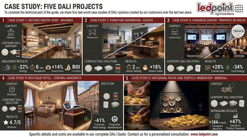
16. Installation of a DALI system step by step: the Ledpoint operational guide
After understanding what the DALI system is, how the DALI protocol works, and what the characteristics of the DALI system are, it is time to face the practical aspect: how is a DALI system concretely installed on a construction site? This chapter describes in detail the eight phases of a professional DALI installation, from preliminary design to commissioning, with all the checks and controls that the Ledpoint technician performs on every delivered system.
The difference between a DALI system that "works" and a DALI system that "works perfectly for ten years" is all in these eight phases. Skipping a step or executing it approximately means accepting the risk of call-backs on site, intermittent malfunctions difficult to diagnose, and dissatisfied end clients. The golden rule of the experienced DALI system installer is: better half an hour more of verification today than half a day of warranty intervention tomorrow.
Phase 1 - Preliminary design of the DALI system
Even before purchasing the components of the DALI system, it is necessary to make a project. The preliminary design of a DALI system answers four fundamental questions: how many lighting fixtures are needed? How many DALI buses are needed? Which type of DALI master is most suitable for the end client? Which DALI scenes should be programmed?
The calculation of the number of DALI buses is crucial: each DALI bus can manage a maximum of 64 addressed devices, but the practical operational limit is 50-55 to leave room for future expansion. For larger systems (for example, a congress center with 178 DALI devices as in case study 3) multiple separate DALI buses are needed with a DALI ↔ DALI interconnection gateway or a multi-bus master master. Underestimating the number of DALI buses needed is one of the most costly design errors because it forces the dismantling and redoing of the wiring.
Phase 2 - Choice of DALI system components
Once the project is defined, the components are chosen. The choice must be consistent: all devices must be DALI-2 certified (IEC 62386) to guarantee interoperability. Mixing DALI v1 and DALI-2 components on the same bus is technically possible but not recommended because the advanced functions of DALI-2 are lost and potential communication criticalities are introduced.
Every DALI system needs at least: a DALI bus power supply (Skydance DA-PB or DA-PL), one or more DALI masters (TD-W touch panel, TD1-TD5, or TD-Z/TD-W2 gateways Skydance depending on the control need), as many DALI dimmers/drivers as there are lighting circuits to be regulated (DA1, DA4, DA5-L, DA4-C, DA4-WPS Skydance depending on the load type), possibly DALI conversion interfaces ↔ other protocols (DT, DV, DH, DA-ML Skydance).
Phase 3 - Wiring of the DALI bus
Wiring is the moment when the project is translated into physical reality. The DALI bus is a two-wire cable (polarized or non-polarized depending on the manufacturer, but DALI-2 prescribes non-polarized) that connects in cascade all the DALI devices of the system. The allowed topology is free: line, star, ring, mixed. The constraint is only on the maximum voltage drop: 2V between power supply and furthest device, which translates into maximum lengths indicated in the table in chapter 5.
The cable to use for DALI can be a standard 2x1.5 mm² or 2x2.5 mm² LSZH (halogen-free) plant cable for laying in junction boxes of the electrical system, or a shielded data cable for laying parallel to power lines in electromagnetically "dirty" environments. Ledpoint recommends 2x1.5 mm² LSZH for 90% of indoor installations, rising to 2x2.5 mm² over 200 meters of development or in case of DALI buses with 60+ devices.
Phase 4 - Connection of DALI devices to the bus
All Skydance DALI devices and those of other certified manufacturers have two terminals dedicated to the DALI bus (usually labeled DA+ and DA-, or simply DA). The terminals of the DALI bus are polarized in the direction of the signal but not in voltage: reversing the two wires does not damage the device but can prevent communication in some older models. Good practice: always respect the polarity marked on the devices, even if DALI-2 declares it optional.
The devices are connected in parallel to the bus: the DALI bus is not a "serial chain" in which if one device fails the communication is interrupted, but a shared bus network. If a single device fails, the others continue to work. This is a fundamental characteristic of the DALI system compared, for example, to the DMX protocol on daisy-chains. For the DALI connection, plug-in terminal blocks, screw terminals, or rapid connections like Wago can be used: all are allowed as long as they are mechanically reliable.
Phase 5 - Power supply of the DALI bus
How is a DALI power supply connected? The DALI bus power supply (e.g., Skydance DA-PB or DA-PL) is connected on one side to the 230V mains (with a dedicated protection switch) and on the other to the DALI bus with two dedicated terminals. The DALI bus power supply delivers about 16VDC (typical range 9.5-22.5VDC according to the standard) and a maximum current of 250 mA, sufficient to power the communication consumption of all DALI devices on the bus.
An important practical rule: only one DALI bus power supply per DALI bus. Putting two power supplies in parallel on the same DALI bus in the belief of "reinforcing" the power supply is a serious mistake that can damage the devices. If more bus current is needed (for systems with many devices that consume a lot on the bus, rare but possible) more powerful power supplies (e.g., 500 mA) are used as a single power point. Alternatively, the system is divided into multiple separate DALI buses with their own power supply each.
Phase 6 - Addressing of DALI devices
Once the system is wired, each DALI device must receive a unique address from 0 to 63. How to address a DALI power supply? The DALI master (Skydance TD-W touch panel or DALI-2 commissioning software connected via gateway) starts the "addressing" procedure which, one by one, identifies all DALI devices present on the bus and assigns them a random or sequential address at the installer's choice.
Skydance DALI devices allow automatic addressing via master but also manual via digital display or buttons on the device itself. Manual addressing is useful when you want an ordered layout (e.g., fixture 1 = first on the left, fixture 2 = second, etc.) to facilitate future diagnostics. Automatic addressing is faster but assigns addresses in random order of device response, forcing the installer to a subsequent mapping.
Phase 7 - Configuration of DALI groups and scenes
Once the devices are addressed, the installer configures the DALI groups (up to 16 per bus) and the DALI scenes (up to 16 per bus, each with a specific level for each device in the group or single). The configuration of groups and scenes is what transforms a DALI system from a "technical box" into a "light experience".
Typical DALI groups in a pastry shop: "display showcase", "service counter", "consumption room", "back laboratory". Typical scenes: "opening", "production work", "public sale", "evening display", "closing". The good practice is to write together with the end client the list of desired scenes before starting the programming, because modifying already programmed scenes requires new access to the DALI master with dedicated software.
Phase 8 - Testing and delivery of the DALI system
Final phase: testing. The testing of a Ledpoint DALI system includes: verification of all DALI devices responded on the bus (must be 100%), verification of functionality of each group, verification of functionality of each scene recalled from touch panel and (if provided)