







B2B LED Strip Buying Guide: How to Validate Custom OEM/ODM Strips Before Production
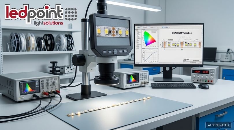
A B2B LED strip buying guide serves to transform a commercial request into a verifiable technical specification. For OEM/ODM custom strips it means setting measurable parameters (flux, SDCM, voltage drop, IP, copper, adhesive), approving a signed reference sample and testing it before mass production, with written acceptance criteria in the contract.
Anyone who works with linear lighting every day knows this well: the sample arrives perfect, mass production does not. A slightly warmer reel, a twenty-metre run that "fades out" toward the end, a silicone coating that lets condensation in after the first winter. These are not rare accidents, they are the almost inevitable consequence of custom specifications that nobody has truly validated. This guide was created to fill a precise gap: online you can find plenty of explanations about COB versus SMD or what IP65 means, but almost nothing about how to confirm the specifications of a custom LED strip before ordering thousands of metres.
We wrote this B2B LED strip buying guide thinking of five professional figures who, at different stages, find themselves signing off, purchasing, testing, selling or installing LED strips: the lighting designer or project engineer, the technical buyer, the quality manager of the OEM/ODM brand, the product manager of a B2B e-commerce and the installer or system integrator. Each will find sections built around their real questions, with tables, indicative thresholds, forms and checklists to attach to the specification.
The guiding thread is simple: every change to the strip is a new strip. Changing the PCB width, the copper thickness, the LED density or the waterproofing material changes the thermal, electrical and optical behaviour of the product. This is why validating the specifications of custom LED strips is not a bureaucratic formality, but the only tool that protects the project, the margin and the reputation. In the following sections we will see how to do it in a repeatable, documented and defensible way in the event of a dispute.
In this article...
1. Why a B2B LED strip buying guide is needed
Before getting into the technical aspects, it is useful to understand why professional LED strip purchasing is different from consumer purchasing. In B2B the strip is not the finished product: it is a component that goes into a luminaire, a piece of furniture, a suspended ceiling or a façade, and that must behave identically over hundreds of metres and for tens of thousands of hours.
The real problem: the traps of custom specifications
The most widespread guides on LED strips, which are rarely a true B2B LED strip buying guide, answer questions such as "how do LED strips work", "can they be cut", "is 12 or 24 volts better". These are legitimate questions, but for those signing off a specification the issue is different. The greatest risk does not lie in choosing between two catalogue products, but in modifying an existing product: a wider PCB to accommodate a connector, a doubled density to eliminate the dotting effect, a different encapsulation to go from indoor to outdoor. Each variation is reasonable on its own; added together, they produce a strip that has never been tested.
When the final performance deviates from the sample, the consequences cascade through the entire supply chain. The designer has to justify a shade difference to the client; the buyer has to open a complaint without objective criteria; the quality manager has to document a non-conformity that the supplier disputes; the installer has to dismantle and reassemble. This is why validation must precede the order, not follow the problem.
What we mean by OEM and ODM
In industry language, an OEM (Original Equipment Manufacturer) relationship provides that the customer supplies the specification and the manufacturer realises it. In the ODM (Original Design Manufacturer) model, the manufacturer proposes the design, which the customer adapts and customises. In both cases the responsibility for final conformity hinges on one point: who wrote the acceptance criteria and who verified them. An effective B2B LED strip buying guide helps precisely to distribute these responsibilities clearly.

Who this guide is for and how to use it
We have organised the content to answer the typical questions of each role. The lighting designer will find the parameters to write into the datasheet and the rules on new validation. The technical buyer will find contractual clauses and criteria for comparing suppliers. The quality manager will find ageing protocols, tightness tests and non-conformity forms. The product manager will find the criteria that distinguish an entry-level strip from a professional one. The installer will find a receiving and on-site verification checklist.
| Role | Key question | Most useful sections |
|---|---|---|
| Project engineer / Lighting designer | Which parameters do I include to protect myself at testing? | 2, 3, 4, 5, 6 |
| Technical buyer / Purchasing manager | Which clauses prevent rework and disputes? | 10, 11, 12 |
| Quality / Production engineer | Which protocols and thresholds do I apply to incoming batches? | 6, 7, 8, 9 |
| Product manager / Category manager | Which minimum specifications reduce returns and complaints? | 3, 15, 16 |
| Installer / System integrator | What do I check on delivery so as not to lose the warranty? | 5, 7, 14 |
The data that really matters
Throughout the article we will use data published in Ledpoint datasheets and declared engineering calculations, with their assumptions. A concrete example comes directly from our product datasheets: if a 5-metre reel is powered from one side only, the power drawn is about 15% lower than with optimal powering, a sign that the voltage drop along the traces is already subtracting current from the furthest LEDs. Another useful figure comes from our technical guide on amps and LED strips: at the same 14.4 W/m over 5 metres, going from 12 V to 24 V halves the current from 6 A to 3 A and reduces losses in the supply cable fourfold.
These figures demonstrate a principle we will encounter often: the same strip can behave very differently depending on how it is designed and powered. A B2B LED strip buying guide limited to the declared lumens per metre is not enough; measurement conditions, tolerances and verification methods are needed.
2. The boundaries of customisation: what requires new validation
The first rule of any validation process for custom LED strip specifications is to establish, before starting, which modifications invalidate the tests already performed. Without this map, every small customer request becomes a discussion, and every discussion risks closing with an "it's practically the same" that nobody has verified.
Why "small changes" produce big differences
An LED strip is a system in balance between three quantities: the current flowing through the LEDs, the heat the PCB can dissipate and the voltage available at every point along the run. Modifying one element shifts the balance of the other two. Doubling the density from 120 to 240 LED/m, for example, increases the power per metre and therefore the current in the traces, the voltage drop and the junction temperature. Moving from a polyurethane encapsulation to a silicone tube changes the optical transmission, the dissipation and the perceived shade.
The modification matrix: when to redo validation
The following table is designed to be attached to the specification. It indicates, for the most frequent modifications, the expected effect and the minimum level of revalidation that we recommend requesting from the supplier.
| Requested modification | Expected technical effects | Revalidation | Minimum tests to repeat |
|---|---|---|---|
| PCB width from 8 to 10 mm | Changes in trace cross-section, dissipation area, connector and profile compatibility | Partial | Voltage drop, temperature in profile, connector test |
| Copper thickness from 1 oz to 2 oz (or vice versa) | Trace resistance halved or doubled, different dissipation | Complete | Flux uniformity over maximum run, thermography, ageing |
| Density from 120 to 240 LED/m | More W/m, more current, different cut pitch, new layout | Complete | All electrical, optical and thermal tests |
| Adhesive/encapsulant from PU to silicone | Transmission, colour drift, adhesion, UV and cold behaviour | Complete for outdoor | SDCM after encapsulation, IP tightness, ageing, bending |
| Change of LED chip model or supplier | Binning, spectrum, efficiency, bonding reliability | Complete | All; request LM-80 of the new chip |
| CCT change on the same platform | Different phosphors, different efficiency and CRI | Partial | Photometry, SDCM, CRI/R9 |
| Voltage from 12 V to 24 V or 48 V | New series circuit, new resistors, new cut pitch | Complete | Electrical, uniformity, thermal |
| Different double-sided tape | Adhesion, thermal resistance of the interface | Targeted | Peel test, test at temperature on the actual support |
| Reel length from 5 to 10/50 m | Joint solderings, feed points | Targeted | Joint inspection, uniformity along the length |
| IP rating from IP65 to IP67 | Different sealing system and caps | Targeted | Immersion test and insulation resistance |
Rule of thumb: if the modification touches the current path, the heat path or the light path, validation must be repeated. This sentence, inserted as a clause, closes in advance 90% of discussions about what is "substantially unchanged".
The most frequent case: 8 mm versus 10 mm
A question we often receive from design studios is: "If I widen the PCB from 8 to 10 mm do I have to redo the sample?". The answer is yes, at least partially. A wider PCB allows wider traces, and therefore a lower voltage drop, but only if the layout is actually redesigned. If the manufacturer simply "widens the edge" while keeping the same traces, the electrical behaviour remains that of the 8 mm version, while accessories and compatible profiles change. This is why the datasheet should not only state the width: it must also declare the copper thickness and the voltage drop measured over the maximum feed length.
Every B2B LED strip buying guide should start here. To navigate between the different construction solutions, the Ledpoint page dedicated to PCB types for LED strips is useful, illustrating the differences between the circuits available in the catalogue and helping to choose the most suitable base before customising.

Customising starting from a validated platform
The most effective way to reduce risk is to start from an existing platform, already measured and documented, and customise only what is truly necessary. The Ledpoint LED strips catalogue is organised precisely by voltage, power, density and LED model, so as to identify the base closest to the requirement. The fewer variables introduced, the fewer tests need repeating and the shorter the approval cycle. It is a logic that benefits everyone: the designer who reduces time, the buyer who contains costs, the manufacturer who can guarantee repeatable results.
3. The critical parameters to write into the specification
In every B2B LED strip buying guide this is the most consulted chapter. A technical specification is useful only if every value is accompanied by a measurement condition and a tolerance. "1,400 lm/m" means nothing if it does not say at what voltage, at what temperature, with what length powered and with what instrument. In this section we list the parameters that, in our experience, should never be missing from a B2B LED strip buying guide or a specification.
Photometric parameters
Luminous flux and efficiency
Luminous flux must be expressed in lumens per metre and accompanied by efficiency in lm/W. In the Ledpoint datasheets, for example, the 3000K 2835 240 LED/m 24V 14.4 W/m LED strip declares 2,000 lm/m and 155 lm/W, while the 120 LED/m version at the same power declares 1,410 lm/m and 110 lm/W. It is an instructive comparison: at the same watt per metre, doubling the LED density and running them at lower current significantly increases efficiency. In the specification it is therefore advisable to state both values, with a tolerance (typically ±10% on flux) and the measurement condition: nominal voltage, two-sided feed, ambient temperature of 25 °C, defined measurement length.
Colour temperature and colour rendering
Correlated colour temperature (CCT) must be stated with its tolerance range and not only with the nominal value. The colour rendering index must be specified as minimum Ra and, for retail, museum, food or hospitality applications, also as a minimum R9 value (saturated red), which CRI 80 chips often neglect. For projects where colour fidelity is decisive, the Ledpoint Sunled line offers strips with CRI Ra>97, such as the 4000K 2835 CRI Ra>97 240 LED/m 24V 19.2 W/m LED strip, which declares 2,080 lm/m and 130 lm/W.
Colour consistency (SDCM)
It is the most often forgotten and most often disputed parameter. We will explore it in section 4, but it should already be said here that colour consistency must be specified both within the reel and between reels and different batches, because they are two distinct problems with distinct causes.
Electrical parameters
Nominal voltage and permitted tolerance, power per metre and total reel power, current drawn, maximum length feedable from one side and from two sides: these are basic data, but they must be made verifiable. The Ledpoint datasheets, for example, state the supply tolerance in the format "24V (+0%, -15%)", valuable information for sizing 24V power supplies and for understanding how much voltage drop the strip tolerates before the difference becomes visible.
In the specification it is advisable to add three items that almost nobody writes: copper thickness in ounces or microns, useful trace width and voltage drop measured at the end of the run in the intended feed configuration. These are the three data that allow comparing two strips that declare the same lumens per metre but that, over a real run, behave completely differently.

Mechanical and mounting parameters
Dimensions, cut pitch and connections
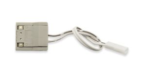
Width, thickness, cut pitch and reel length affect compatibility with profiles, connectors and caps. A cut pitch of 3.33 cm or 2 cm offers more freedom of adaptation than one of 10 cm, but multiplies the pads to be checked. For solderless connections it is essential that the PCB width and pad position are compatible with the PCB connectors for LED strips planned in the project.
Double-sided tape
The adhesive tape is the thermal bridge between strip and heatsink and the first cause of detachment on site. It must be specified with brand and code, not with the generic wording "3M". Ledpoint declares the double-sided tape code for each strip (for example 3M 9495LE, 3M 5604A VHB or 3M 9080HL) and makes the datasheet of the 3M 9495LE tape available. To choose the adhesive according to the support, the page on double-sided tape types is useful.
Environmental and reliability parameters
Operating temperature (for example -10 °C ~ +45 °C, as indicated on many Ledpoint strips), IP protection rating, declared life and the method by which it was estimated. For life it is essential to distinguish between a generic figure ("50,000 hours") and a figure derived from IES LM-80 tests on the chip and TM-21 extrapolation. Some Ledpoint strips are accompanied by the LM-80 report of the 2835 LED used: it is the kind of document a buyer should always request.
| Parameter | How to write it in the specification | Indicative tolerance | Verification method |
|---|---|---|---|
| Luminous flux | lm/m at nominal V, 25 °C, two-sided feed | ±10% | Integrating sphere on defined section |
| Efficiency | lm/W under the same conditions | -10% | Photometry + power measurement |
| CCT | Nominal value and permitted range | Within declared ellipse | Spectroradiometer |
| CRI Ra / R9 | Minimum values | Guaranteed minimum | Spectroradiometer |
| SDCM intra-reel and inter-batch | N MacAdam steps | ≤ 3 steps for professional use | Chromaticity coordinates on distributed samples |
| Power | W/m and total reel W | ±10% | Wattmeter at nominal V |
| Voltage drop | V at end of run over maximum length | Agreed maximum value | Multimeter, single and two-sided feed |
| Copper thickness | oz or µm | Guaranteed minimum | Declaration + metallographic section on sample |
| IP rating | IP and test method | None | Immersion/jet test + insulation |
| Life | L70/L80 with LM-80/TM-21 reference | Documentary | Laboratory report |
4. Colour consistency between reels: SDCM and MacAdam
No defect is more visible, and more difficult to correct afterwards, than two adjacent runs with different shades. On a continuous lighting groove, on a display counter or on a white lacquered piece of furniture, the eye catches minimal differences. This is why colour consistency deserves a dedicated section in any B2B LED strip buying guide.
What MacAdam ellipses and SDCM steps are
MacAdam ellipses describe, in the CIE 1931 chromaticity diagram, the regions within which an average observer does not distinguish colour differences. A 1-step ellipse corresponds to the perception threshold; speaking of "3-step SDCM" (Standard Deviation of Colour Matching) means that all LEDs fall within an area three times larger than the minimum threshold. For professional applications where strips are directly visible or placed side by side, 3 steps is the commonly adopted reference; 5 steps may be acceptable for indirect, non-adjacent light; beyond that, differences become visible.
Many Ledpoint strips directly state "3step" in their name, such as the 3000K 3step 2835 120 LED/m 24V 14.4 W/m LED strip. It is a figure that makes offers comparable and should be transcribed as is into the specification. To explore the classification of whites, the page on white colour shades is available.
Why the same reel is consistent but different reels are not
It is one of the most frequent complaints: "within the reel the colour is perfect, but between one reel and another there is a difference". The typical causes are three. The first is binning: the chip manufacturer selects LEDs into colour classes; a reel is populated with a single bin, but a subsequent batch may be populated with an adjacent bin, both formally "3000K". The second is encapsulation: silicone and polyurethane shift the chromaticity coordinates by a few thousandths, and small variations in thickness or formulation between batches produce differences. The third is operating current: if two reels are powered differently, or with different voltage drops, the LEDs run at different currents and the shade changes slightly.
How to verify colour consistency objectively
The sampling protocol
A reliable verification requires a declared sampling plan. A simple and repeatable procedure involves taking, from each sampled reel, three sections corresponding to the beginning, middle and end, and measuring their chromaticity coordinates x,y with a spectroradiometer under stabilised conditions (at least 30 minutes of operation, controlled ambient temperature, nominal voltage applied directly to the sections). The key point is to measure short sections powered directly, to exclude the effect of voltage drop and isolate the colour variable.
Calculation and acceptance criterion
The coordinates obtained must be compared with the centre of the ellipse declared by the supplier and with the coordinates of the approved reference sample (golden sample). The acceptance criterion can be written as follows: "all measurements must fall within the 3-step ellipse centred on the chromaticity point of the reference sample; alternatively, the maximum distance between any two measurements of the same batch must not exceed the agreed value". Anchoring the criterion to the golden sample, and not only to the catalogue nominal value, is what makes the verification incontestable.
Visual comparison
The instrument does not replace the eye, it completes it. It is good practice to set up a comparison bench where sections from different reels are placed side by side in the same profile with the same diffuser, observed under reduced ambient light and photographed with locked white balance. The photo, archived with date and batch codes, becomes part of the validation file.
Contractual countermeasures
For projects with large continuous metreage it is advisable to ask the supplier to reserve a single production batch (same chip bin, same encapsulant batch) for the entire order, or to declare the bin of each reel on the delivery note, so that they can be distributed on site avoiding critical adjacencies. It is an almost zero-cost precaution that prevents most disputes about shade.
5. Voltage drop and long runs: the 20-metre case
If colour consistency is the most visible defect, the difference in brightness between the beginning and end of a run is the most frequent. It particularly affects long linear installations, such as ceiling grooves, handrails, façades and continuous shelving, and depends on a combination of voltage, power per metre and copper thickness that must be verified at the design stage.
The physics in two lines
The copper traces on the PCB have electrical resistance. The current feeding all the downstream LEDs passes through the upstream traces, and a voltage drop proportional to the current and the resistance is generated across these traces. The longer the run, the higher the power per metre and the thinner the copper, the greater the voltage lost along the path. The LEDs at the end of the run receive less voltage, run at lower current and emit less light.
Why at 24 V a small voltage loss weighs so much
In most constant-voltage strips, each segment consists of a group of LEDs in series and a limiting resistor. In the typical 24 V configuration with six LEDs in series, the LEDs absorb about 17.5-18.5 V and the resistor works on the remaining 5.5-6.5 V. It is this voltage "reserve" across the resistor that determines the current. If 3 V are lost along the run, the reserve is reduced by about half and the current, and with it the flux, drops by proportionally much more than the 12.5% of voltage lost. This is why, in any B2B LED strip buying guide, voltage drop deserves a chapter of its own: an apparently modest drop produces a clearly visible difference in brightness.

The typical case: 20 metres, 24 V, 4.8 W/m
To make the problem concrete we propose a typical case reconstructed with a simplified linear model. Assumptions: continuous 20-metre run, 24 V strip at 4.8 W/m, total current 4 A, uniformly distributed load. Let us compare two PCBs with loop resistance (out and back) of 0.08 Ω/m for the thicker copper and 0.16 Ω/m for the thinner copper, plausible values respectively for circuits of about 2 oz and 1 oz. For a distributed load fed from one side, the drop at the end of the run is about I × R total / 2.
| Configuration | ~2 oz copper (0.08 Ω/m) | ~1 oz copper (0.16 Ω/m) | Expected visual outcome |
|---|---|---|---|
| 20 m, one-sided feed | ≈ 3.2 V (13%) | ≈ 6.4 V (27%) | Evident difference; with thin copper the end of the run is much darker |
| 20 m, feed from both ends | ≈ 0.8 V (3%) at the centre | ≈ 1.6 V (7%) at the centre | Acceptable with thick copper, borderline with thin copper |
| 20 m, centre + ends feed | ≈ 0.2 V | ≈ 0.4 V | Uniform |
| 20 m at 48 V, same power, one side | ≈ 1.6 V (3%) | ≈ 3.2 V (7%) | Good uniformity even with a single feed point |
Th
e model slightly overestimates real drops, because in practice the current decreases as the voltage falls, but it is sufficient to show the order of magnitude. The same project, with the same strip code "on paper", can be perfect or unacceptable depending on the copper thickness actually supplied. It is the trap described by many operators: a variation in the copper supply between sample and production that changes nothing on the one-metre test bench, but that over twenty metres becomes visible to the naked eye.
The cost of the trap: a rework example
Suppose a retail project with 40 runs of 20 metres each, installed in plasterboard grooves with one-sided feed. At delivery, a difference in brightness between the beginning and end of each run emerges. The options are two: add a second feed point to each run, or replace the strip. In the first case new cables are needed through the ceiling, openings and plasterboard repairs, new power supplies or load redistribution; in the second case the material cost is added. In both cases the rework cost far exceeds the price difference between a strip with adequate copper and one with reduced copper. It is the strongest argument a buyer can bring to the table to justify a more stringent specification.
Design solutions
Raise the voltage
At the same power, doubling the voltage halves the current and reduces the relative drop fourfold. For long runs, 48V LED strips, combined with 48V power supplies, are often the most rational choice. For very long runs without intermediate feed points there are also 230V LED strips, available in reels up to 50 metres with IP65 protection.
Choose constant-current strips
Strips with integrated current regulation keep the current in the LEDs constant over a wide voltage range, compensating for the drop along the run. Ledpoint collects them in the LED strips with constant current control system category, which includes for example the COB 10 m 4000K 12V strip with current control.
Multiply feed points and size the cables
Feeding from both sides, or adding a central feed, is often the most economical solution. It must be accompanied by correct sizing of the power cables, because the drop in the cable adds to that in the strip. The specification must state the feed configuration with which the strip was validated: a validation performed with two-sided feed is not valid for a one-sided installation.
6. Pre-production testing of LED strips: the operational checklist
We come to the heart of the guide. Pre-production testing of LED strips is the stage in which the approved sample is transformed into a measurable reference, and in which it is verified that the first production pieces (pre-series) faithfully reproduce it. It is here that problems are avoided at minimum cost, problems that would otherwise emerge on site at maximum cost.
The three phases: sample, golden sample, pre-series
Every well-set pre-production LED strip test distinguishes three moments. The development sample serves to verify that the technical solution works. The golden sample (reference sample) is the approved sample, signed by both parties, kept in duplicate and accompanied by its measurement report: it becomes the touchstone for all future batches. The pre-series is a small batch produced with final materials, equipment and processes: only if the pre-series passes the test is mass production authorised. Skipping the pre-series is the most frequent cause of the difference between sample and production, because the sample is often made by hand or with laboratory materials.
The pre-production validation checklist
The following table is the central tool of this B2B LED strip buying guide and of the validation of custom LED strip specifications: it can be copied into the specification or turned into a test form. The thresholds are indicative and must be adapted to the application; what matters is that each row has a method, an instrument, a criterion and a responsible person.
| No. | Test | Method | Instrument | Indicative criterion | Sample |
|---|---|---|---|---|---|
| 1 | Visual and dimensional inspection | Width, thickness, cut pitch, markings, polarity | Caliper, magnifier | Conforms to drawing, no damaged LEDs | Each sampled reel |
| 2 | Power drawn | Nominal V, two-sided feed, 30' stabilisation | Wattmeter | ±10% of declared | 3 reels |
| 3 | Flux and efficiency | Section of defined length | Integrating sphere | ±10% lm/m; efficiency ≥ 90% of declared | 3 sections per reel |
| 4 | CCT, CRI, R9 | Sections beginning/centre/end | Spectroradiometer | Within tolerance; Ra and R9 ≥ minimums | 3 sections per reel |
| 5 | SDCM intra-reel and inter-reel | Comparison with golden sample | Spectroradiometer | ≤ 3 steps | All sampled reels |
| 6 | Voltage drop | Maximum length, intended feed | Multimeter | ≤ agreed value at end of run | 1 complete run |
| 7 | Luminance uniformity | Measurement at beginning, centre, end of run | Luminance meter or lux meter at fixed distance | Min/max ratio ≥ agreed value (e.g. 0.85) | 1 complete run |
| 8 | Thermography | Strip mounted in the actual profile | Thermal camera, thermocouple | Tc ≤ chip limit | 1 run |
| 9 | Double-sided tape adhesion | Peel test on actual support | Dynamometer | ≥ adhesive datasheet value | 3 specimens |
| 10 | Bending / torsion | Cycles on defined mandrel | Test bench | No interruption, no flux variation > 5% | 3 specimens |
| 11 | IP tightness and insulation | Immersion or jet + insulation measurement | Tank, megohmmeter | No infiltration; insulation ≥ agreed threshold | 3 specimens |
| 12 | Accelerated ageing | High temperature, nominal V, defined hours | Climatic chamber | Flux maintenance ≥ threshold; Δu'v' ≤ threshold | 3 specimens |
| 13 | Dimming and flicker | With the project driver/dimmer | Oscilloscope, flicker sensor | Stable regulation, no visible flicker | 1 run |
| 14 | Documentation | Verification of declarations and reports | Dossier | LM-80, test report, declarations present | Per batch |
The value of this checklist lies not in the individual thresholds, but in the fact that each test is defined before the product arrives. A threshold agreed in advance is an objective criterion; a threshold discussed after delivery is a negotiation.

How to read a supplier's test report
A good supplier provides measurement reports for their products. Ledpoint, for example, makes available for download for many strips both the photometric test report and the strip datasheet. When reading a report it is advisable to verify four elements: the measurement conditions (voltage, temperature, length), the instrument used, the date and the exact product code measured. A report valid for one variant is not automatically valid for a customisation: if the strip has been modified according to the matrix in section 2, the report must be redone.
Documenting the golden sample
The validation of custom LED strip specifications rests on the golden sample. It must be stored in the dark, in an antistatic bag, at room temperature, with a label showing code, date, signatures and reference to the measurement report. One copy remains with the customer, one with the supplier. It is advisable to photograph it switched on and off, with locked white balance and a metric scale in the frame. In the event of a dispute, the golden sample is the only physical evidence that counts: without it, every comparison is reduced to an opinion.
7. Waterproofing, COB and mechanical tests
In our B2B LED strip buying guide the section on outdoor applications is the one that generates the most questions. Strips for outdoor, humid environments or applications with mechanical movement introduce specific risks. The declared IP rating is the starting point, but on its own it says nothing about the duration of protection over time nor about the strip's resistance to bending, torsion and thermal cycles.
The IP rating beyond the code
The IP code defined by IEC 60529 describes protection against solids and liquids under standardised test conditions: IP65 indicates total protection against dust and against water jets, IP67 against temporary immersion. But a short laboratory test does not reproduce the condensation that forms every night on a façade, nor UV ageing, nor freeze-thaw cycles. For outdoor applications with condensation, the installer must know that tightness depends as much on the strip as on the caps, cable glands and the quality of the seals made on site. The Ledpoint page on IP protection types for LED strips describes the available construction solutions, from extruded silicone tube to full potting.
Polyurethane or silicone: what changes
Polyurethane is inexpensive and works well, but tends to yellow with UV and heat and to stiffen in the cold. Silicone better maintains transparency and elasticity over a wide temperature range, but is more difficult to bond and seal, and requires specific caps and adhesives. Moving from PU to silicone is not a simple material substitution: it changes the perceived shade, the dissipation, the adhesion of the caps and the sealing method, and must therefore be treated as a new validation. Ledpoint offers several strips with extruded silicone tube, such as the IP65 "full edges hollow inside" versions and the IP67 COB with spherical tube, accompanied by dedicated caps for LED strips.

How to test the continuity of the coating
To verify that the waterproof coating is continuous, without micro-holes or thin areas, visual inspection is not enough. A repeatable procedure, also applicable to encapsulated COB strips, involves immersing the specimen (with ends sealed according to the on-site procedure) in slightly salty water, which is conductive, and measuring with a megohmmeter the insulation resistance between the strip conductors (short-circuited) and an electrode immersed in the tank. The test voltage must be chosen consistently with the SELV class of the product and agreed with the supplier.
The acceptance criterion can be expressed as a minimum resistance (in the order of megohms, for example ≥ 2 MΩ, to be agreed) measured after a defined immersion time, followed by a functional check and verification of no infiltration when the specimen is opened. A resistance that decreases over time during immersion is the typical signal of a micro-hole or a defective seal, even when the strip continues to light up regularly.
Bending and torsion: reference values
Why COB strips are more sensitive
COB LED strips offer a continuous line of light without the dotting effect, thanks to hundreds of chips per metre covered by a phosphor layer. This structure, however, concentrates many solder points on an often very thin PCB: repeated bending or torsion during installation can create micro-cracks in the connections, which manifest as extinguished or intermittent chips only after a few thermal cycles. This is why, in COB strips, the bending test is particularly important.
How to set up the test
A repeatable bending test involves winding the lit specimen around a mandrel of defined radius (consistent with the minimum radius expected in installation), for a set number of cycles, checking electrical continuity and flux before and after. For torsion, a defined rotation is applied between two clamps over a fixed length. The reference values (radius, number of cycles, angle) must be derived from the actual application and agreed: a strip intended for a straight profile has different needs from one that must follow a tight curve. The typical criterion is no interruption, no extinguished chips and flux variation within 5%.
The role of the aluminium profile
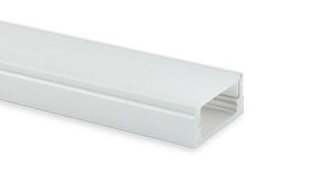
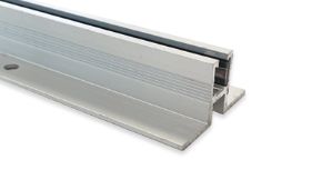
Most mechanical and thermal problems are solved by mounting the strip in an adequate profile. Ledpoint aluminium profiles protect the strip, improve dissipation and optical uniformity with the diffusers. The Ledpoint datasheets explicitly remind users to apply the strips on a metal heatsink, preferably oxidised aluminium, avoiding conductive surfaces that could create short circuits. For custom projects, custom profiles are also available, which must be validated together with the strip: the combination of strip + profile + diffuser is the true object of the test.
8. High-temperature ageing and flux drift
The behaviour of an LED strip in the first hours says little about its useful life. Flux and shade drift emerge over time and with temperature, which is why validation must include an ageing test, even an abbreviated one, and a critical reading of the declared reliability data.
LM-80 and TM-21: what they say and what they do not say
The LM-80 standard describes how to measure the lumen maintenance of an LED under controlled temperature and current conditions for thousands of hours; the TM-21 method allows extrapolating life (for example L70, the time after which flux falls to 70% of the initial value) within precise limits, linked to the duration of the test. These data concern the individual chip, not the complete strip: they do not take into account the PCB, the encapsulation, the profile and the actual operating temperatures. They are a necessary but not sufficient condition; this is why it is useful to combine them with a test on the finished strip.
An ageing protocol applicable in-house
A pragmatic protocol, which a quality manager can apply with a climatic chamber, involves powering three specimens at nominal voltage, mounted on the project support or profile, at the maximum declared operating ambient temperature (for example +45 °C for many Ledpoint strips). Photometric and colorimetric measurements are performed at time zero and after defined intervals, for example 168, 500 and 1,000 hours, bringing the specimens back to 25 °C before each measurement.
| Phase | Duration | Condition | Measurements | Indicative criterion to be agreed |
|---|---|---|---|---|
| Initial measurement | t = 0 | 25 °C, nominal V, 30' stabilisation | Flux, x,y, power | Reference values |
| Burn-in | 168 h | T max operating, nominal V | Flux, x,y, visual inspection | No failure; flux ≥ 97% |
| Intermediate | 500 h | As above | Flux, x,y | Flux ≥ 95% |
| Final | 1,000 h | As above | Flux, x,y, encapsulant inspection | Flux ≥ 93%; Δu'v' within threshold; no yellowing |
| Thermal cycles (optional) | Defined number of cycles | From T min to T max operating | Continuity, flux | No interruption |
The thresholds in the table are examples to be adapted: what must be fixed is the method, because only an identical method makes different suppliers and batches comparable. A strip that loses 10% of flux in the first 500 hours in a climatic chamber will hardly meet a declared life of tens of thousands of hours in service.

Internal bonding: a detail that makes the difference
Inside each LED, the chip is connected to the terminals by very thin wires. The material of these wires (gold, silver or alloys) influences resistance to corrosion and thermal cycles. Ledpoint dedicates an in-depth look at Au and Ag connections in 2835 LEDs: it is information that an attentive buyer should request, because two chips that are identical on the outside can have very different reliability due to bonding, and a change of chip supplier between sample and production can go unnoticed until the first failures in the field.
9. OEM ODM LED strip quality control: incoming inspection and non-conformities
Once the pre-series is approved, control shifts to production batches. The topic of OEM ODM LED strip quality control mainly concerns the customer's quality manager, who must receive the batches, perform incoming tests and manage non-conformities so that they are documented and non-disputable.
The sampling plan
The sampling plan is the core of the OEM ODM LED strip quality control process. Inspecting 100% of the metres received is rarely sustainable. Industrial practice is to adopt statistical sampling plans, for example according to ISO 2859-1, with an acceptable quality limit (AQL) differentiated by defect type. A commonly adopted classification provides for critical defects (safety, reversed polarity, short circuits) with zero tolerance, major defects (extinguished LEDs, shade out of tolerance, insufficient flux) with stringent AQL and minor defects (cosmetic, markings) with a wider AQL. The sampling plan must be written into the contract, together with the defect classification, because it is what determines the acceptance or rejection of the batch.
| Defect class | Examples | Typical approach |
|---|---|---|
| Critical | Short circuit, reversed polarity, insufficient insulation, abnormal overheating | Zero tolerance, batch rejection |
| Major | Extinguished LEDs or segments, SDCM beyond threshold, flux out of tolerance, non-conforming adhesive | Stringent AQL |
| Minor | Scratches on the PCB, imprecise label, damaged packaging without functional effects | Wider AQL |
Incoming tests: what to do on each batch
In OEM ODM LED strip quality control not all the tests of the pre-production checklist need to be repeated on every batch. For incoming inspection a rapid subset is sufficient: documentary verification (code, batch, declared bin), visual and dimensional inspection, 100% lighting of the sampled reels, power measurement, colorimetric measurement on sections and comparison with the golden sample. Destructive or long tests (ageing, immersion, bending) are performed at reduced frequency, for example on the first batch, on every material change declared by the supplier and periodically.
How to document a non-conformity incontestably
A non-conformity is disputable when an objective reference is missing. To be defensible, the non-conformity report (NCR) must contain some minimum elements, summarised in the following table.
| NCR form field | Required content |
|---|---|
| Identification | Product code, batch, number of reels received and sampled, date of receipt |
| Requirement violated | Specific reference to the specification or contract line |
| Evidence | Measured values, instrument, measurement conditions, photos with locked white balance |
| Comparison | Golden sample measurement under the same conditions and in the same session |
| Classification | Critical, major or minor according to the agreed plan |
| Samples | Non-conforming sections kept and labelled, available for counter-verification |
| Request | Action requested: replacement, sorting, rework, corrective action |
| Signatures and dates | Operator, quality manager, date sent to supplier |
Measuring the golden sample in the same session as the disputed batch is the detail that removes any argument from the supplier, because it eliminates objections about instrument, calibration and environmental conditions.

Corrective action and closing the loop
In the OEM ODM LED strip quality control cycle, a non-conformity is not closed with the replacement of the reels, but with the understanding of the cause. The supplier must be asked for a structured analysis (for example according to the 8D scheme), with identification of the root cause, corrective action and effectiveness verification on the next batch. A supplier that responds to a complaint with a simple credit note, without cause analysis, is a supplier destined to repeat the same problem.
10. Inspection clauses to include in the contract
For the technical buyer following a B2B LED strip buying guide, the contract is the most powerful quality tool. The best specifications in the world are useless if the contract does not establish who measures, how, when and what happens in the event of a negative outcome. In this section we propose a set of clauses to be adapted with your legal department.
The essential clauses
Golden sample reference clause
"The reference sample approved on [date], identified by code [...] and kept in duplicate by the parties, constitutes the binding reference for the photometric, colorimetric, electrical and mechanical characteristics of the supply. Production batches must fall within the tolerances indicated in the Technical Annex with respect to the measurements of the reference sample performed under the same conditions."
Bill of materials freeze clause
"The supplier undertakes not to modify, without prior written approval of the customer, the following elements: LED chip model and manufacturer, binning class, PCB copper thickness, circuit layout, encapsulant material and supplier, double-sided tape code, limiting resistor values. Any modification requires a new validation according to the Technical Annex." This clause, known as "frozen BOM", is the most effective defence against drift between sample and production.
Inspection and acceptance clause
"The customer performs the incoming inspection within [...] working days of receipt, according to the sampling plan and defect classification of the Technical Annex. A negative inspection outcome, documented with a non-conformity report, obliges the supplier to replace or sort at its own expense within [...] days, without prejudice to the customer's right to reimbursement of additional inspection costs."
Traceability clause
"Each reel must bear on its label the product code, batch number, production date and chromatic bin of the chip. The supplier keeps for at least [...] years the production records and samples of each batch." Traceability of the bin on the label allows the installer to distribute the reels avoiding critical adjacencies.
Documents clause
"The supplier delivers, before production starts, the technical dossier comprising: signed datasheet, photometric and colorimetric measurement reports, LM-80 reports of the chip used, double-sided tape datasheet, declarations of conformity and CE marking, RoHS declaration and energy class information pursuant to current regulations."
The technical annex: the part that makes the difference
All the clauses refer to a technical annex which must contain the parameter table of section 3, the test checklist of section 6, the sampling plan of section 9 and the feed configuration with which the validation was performed. A contract without a technical annex is a contract without acceptance criteria, and no B2B LED strip buying guide can compensate for this lack.
11. Hidden costs and specification traps
No B2B LED strip buying guide would be complete without talking about price. The price per metre is the most visible figure of an offer and often the least significant. The real cost differences hide in the materials and processes that do not appear on the front page, and that determine how much the strip will actually cost once installed and maintained.
Where savings are made (and where you pay later)
| Item | How savings are made | Symptom in service | Hidden cost |
|---|---|---|---|
| Copper thickness | Copper thinner than declared | End of run darker, overheating | Additional feed points, replacement |
| LED chip | Wider bin, non-certified chips | Shade differences, rapid decay | Selective replacements, disputes |
| Bonding | Alloys instead of gold | Intermittent failures after thermal cycles | Warranty interventions |
| Double-sided tape | Generic adhesive | Detachments, especially in hot profiles | Rework, mechanical clips |
| Encapsulant | Cheap PU instead of silicone | Yellowing, infiltration | Complete replacement outdoors |
| Resistors | Sized to the limit | High sensitivity to voltage drop | Additional power supplies and wiring |
| Quality control | No end-of-line testing | LEDs extinguished at first power-up | 100% inspection borne by the customer |
Total cost of ownership
To compare two offers correctly it is necessary to reason on total cost: strip price, power supplies required (which depend on efficiency and voltage drop), installation labour, rework risk, warranty costs. A more efficient strip requires smaller power supplies, heats up less and lasts longer: savings on the other components can more than offset a higher price per metre. For estimating the power and currents involved, the aforementioned Ledpoint guide on amps includes tables for 24 V and 48 V strips useful at the quotation stage.
Two suppliers, same lumens: how to compare them
It is a typical product manager question. If two suppliers declare the same lumens per metre, the comparison must be made on five elements: efficiency in lm/W (which reveals how "comfortably" the LEDs are working), LED density and current per chip, copper thickness and declared voltage drop, presence of LM-80 documentation and test reports, declared colour consistency in SDCM steps. The strip that achieves the same lumens with more LEDs at lower current will almost always be more reliable and more stable over time.
12. How to recognise a supplier that truly validates
Choosing the right partner is the final step of every B2B LED strip buying guide. Many manufacturers report a "Testing & Validation" section on their website, but it is often a list of titles without procedures, thresholds or results. For the buyer it is essential to distinguish those who really validate from those who simply send generic datasheets.
The signs of a reliable supplier
A supplier that truly validates makes specific documents available for each product, not a single datasheet valid for the whole family. They declare measurement conditions, instruments and dates. They state copper thickness, double-sided tape code, chip model and SDCM class. They accept without resistance the bill of materials freeze clause and the retention of the golden sample. They respond to non-conformities with cause analysis and not just replacements.
| Criterion | Supplier that validates | "Generic datasheet" supplier |
|---|---|---|
| Documentation | Test report per product code, chip LM-80 | Single family datasheet |
| Construction data | Copper, adhesive, chip, bin declared | Only W/m and lumens |
| Colour consistency | SDCM steps declared in name or datasheet | "Uniform colour" |
| Measurement conditions | Voltage, temperature, length indicated | Absent |
| Availability and continuity | Information on stock and restocking | No continuity guarantee |
| Complaint management | Root cause analysis | Replacement without analysis |
The Ledpoint documentation example
Ledpoint, based in Faenza, has worked for years with installers, resellers and designers on professional LED strips. For many catalogue products it publishes test reports, datasheets, double-sided tape datasheets and, where applicable, LM-80 reports of the chip, as well as stating energy class, adhesive code and operating temperature. The stock and availability page also provides information that is often overlooked but fundamental in B2B: continuity of supply of a code is part of its quality, because it ensures that a future extension or maintenance can be carried out with the same product. The complete technical catalogues are available in the Ledpoint catalogues section, including the Orizzonte COB catalogue.
Questions to ask during qualification
Before entrusting a customisation, it is advisable to ask the supplier precise questions and request written answers: which chip and which bin will you use; what copper thickness and what voltage drop measured over the maximum length; what encapsulant and what sealing procedure; what tests performed at end of line; how do you manage changes to the bill of materials; what documents do you deliver for each batch. The quality of the answers is already, in itself, proof of validation.
13. Retrofit with LED strips in professional projects
A B2B LED strip buying guide today cannot ignore retrofit. A growing share of B2B projects does not concern new installations, but the replacement of existing sources. Retrofit with LED strips consists of replacing fluorescent tubes, linear halogen sources or old low-efficiency strips with modern LED strips, reusing, where possible, existing housings, profiles and conduits. It is an area in which specification validation is even more delicate, because the dimensional and thermal constraints are imposed by what already exists.
Why retrofit requires dedicated validation
In retrofit you do not choose the space: you inherit it. A lighting groove designed for a T5 tube has a precise geometry, distance from the edge and ventilation; a refrigerated display case has its own temperatures and condensation; an existing piece of furniture has profiles with fixed internal widths. The chosen strip must therefore adapt to non-modifiable dimensions and conditions, and this often pushes toward customisations (PCB width, cut pitch, power per metre) that must be validated as described in the previous sections.
Retrofit-specific checks
Photometric equivalence
Replacing a source does not mean replicating its watts, but its luminous effect. The useful flux of the old source must be compared with that of the new strip in the same position, considering that the LED strip emits directionally while the fluorescent tube emits at 360°. In many cases a strip with fewer nominal lumens produces more useful light on the plane of interest, because it does not waste flux toward the bottom of the groove.
Thermal and power compatibility
Retrofit must provide for the removal or bypassing of old ballasts and the installation of adequate power supplies. The temperature in the existing housing must be measured, not assumed: closed grooves and poorly ventilated suspended ceilings can exceed the maximum operating temperature of the strip. In these cases an plasterboard aluminium profile or a recessed profile improve dissipation and architectural integration.
Uniformity and absence of dotting
In the retrofit of grooves and display cases the line of light is often visible or reflected. COB strips, such as the COB 50 m 3000K CRI Ra>93 24V 9 W/m strip, allow a continuous line to be achieved even without a deep diffuser, and availability in 50-metre reels reduces joints in long runs.

A five-step retrofit path
Professional retrofit follows a linear path: survey of existing housings (dimensions, temperatures, power supplies); definition of photometric and chromatic requirements; choice of the closest catalogue platform and any customisations; on-site test on a sample run, with illuminance and temperature measurements; approval and production. The on-site test on a sample run is the "site" version of the golden sample and must be documented with the same care.
14. Checks on delivery and on site
This part of the B2B LED strip buying guide is dedicated to those who install. The installer is the last link in the chain and often the first to discover problems. Some quick checks on delivery and before mounting allow non-conformities to be intercepted when replacement costs little, and prevent the warranty from being compromised.
The receiving checklist
| Check | How | Why |
|---|---|---|
| Code and batch correspondence | Compare labels with order and specification | Avoid mixing batches or versions |
| Chromatic bin | Read label, group reels | Avoid adjacencies with different shades |
| Packaging and reel integrity | Visual inspection | Identify bends or crushing |
| Test power-up | Each reel lit on the reel for a few seconds with adequate power supply | Identify extinguished LEDs or segments |
| Visual comparison | Sections of different reels placed side by side | Verify colour consistency before mounting |
| Documentation | Keep delivery notes, labels and photos | Warranty and traceability protection |
Powering up each reel before installing it takes a few minutes and can avoid days of dismantling. Power-up should be brief if the reel is wound, because on the reel the strip does not dissipate.
The golden rules of mounting
Cutting and connections
Many operators wonder how to cut an LED strip and how to connect LED strips without compromising reliability and warranty. The rule is simple: cut only at the marked points, respect polarity, use connectors compatible with the PCB width and number of poles, or correctly executed solder joints with solder joints. For IP65 and IP67 strips, every cut requires the restoration of tightness with caps and sealants suitable for the encapsulant material.
Power and wiring
To power an LED strip correctly it is necessary to respect the validated feed configuration: if the specification provides for two-sided feed, feeding from one side only invalidates the declared performance. Cable cross-sections must be calculated on the actual current and the distance from the power supply, and the power supply sized with an adequate power margin with respect to the load.
Mounting surface
The support must be clean, dry and degreased; for good thermal transfer an aluminium profile is preferable. On low surface energy surfaces an appropriate adhesive must be used. Mounting the strip directly on wood or plasterboard without a profile, when the power per metre is high, is one of the most common causes of premature decay.
Outdoors with condensation: which IP is truly adequate
For outdoors exposed to driving rain and condensation, IP65 is the minimum, but real protection depends on the installation: profile with diffuser that reduces direct exposure, cable entry points facing downwards, caps sealed with compatible products, no standing water. In environments where immersion is possible or frequent washing occurs, it is advisable to move toward IP67 solutions. The tools useful for mounting and checks are collected in the Ledpoint tools category.
15. Entry level or professional: criteria for the product manager
For those building an assortment, a B2B LED strip buying guide is also a positioning tool. Those who manage a product category in a B2B e-commerce or distribution network must decide which SKUs to launch and with which minimum specifications. The objective is twofold: differentiate the offer in a way that is understandable to the end customer and reduce post-sales returns and complaints.
The parameters the customer perceives
The end customer does not read an LM-80 datasheet, but perfectly perceives four things: whether the light is uniform, whether the colour is pleasant and consistent, whether the strip stays glued and whether after a year it still works as on the first day. Each of these perceptions corresponds to precise technical parameters, which become the true differentiation criterion between an entry-level line and a professional line.
| Parameter | Typical entry level | Typical professional | Customer perception |
|---|---|---|---|
| Colour consistency | Not declared or 5+ steps | 3 steps declared | Adjacent runs of the same colour |
| CRI | Ra>80 | Ra>90 up to Ra>97, R9 declared | Natural colours of materials and products |
| Efficiency | 80-100 lm/W | 110-155 lm/W | More light, less heat, smaller power supplies |
| PCB copper | Not declared | Declared, adequate for the runs | Uniformity over long distances |
| Double-sided tape | Generic | Brand and code declared | No detachment |
| Documentation | Summary datasheet | Test report, datasheet, LM-80 | Trust, ease of specification |
| Supply continuity | Not guaranteed | Stable codes and stock | Ability to extend or replace |
The minimum specifications that reduce returns
From professional sales experience, some minimum specifications emerge that, on their own, eliminate most returns: declared colour consistency, quality double-sided tape with indicated code, 24 V voltage for general applications, downloadable documentation and clear instructions on power and dissipation. Adding the maximum feedable length and the recommendation to mount on an aluminium profile to the product datasheet further reduces assistance requests.

Communicating the difference
A professional line must be told with data, not with adjectives. Icons showing CRI, power, voltage, cut pitch and energy class, such as those in the datasheets of the Ledpoint LED strip lines catalogue, allow the customer to compare in a few seconds. A B2B e-commerce that displays verifiable data reduces pre-sales questions and increases the trust of the professional customer.
16. Ledpoint strips for B2B specifications
To conclude the operational part of this B2B LED strip buying guide, we collect some strips from the Ledpoint catalogue that represent good starting platforms for professional specifications and for any customisations. The data reported come from the published datasheets; for each code it is always advisable to download the updated documentation.
| Product | Main data | When to choose it |
|---|---|---|
| 3000K 3step 2835 240 LED/m 24V 14.4 W/m strip | 2,000 lm/m, 155 lm/W, 3.33 cm cut, PCB 10 mm, 3M 9495LE | Maximum efficiency, grooves and accent lighting in hospitality and offices |
| 4000K 3step 2835 CRI Ra>97 240 LED/m 24V 19.2 W/m strip | 2,080 lm/m, 130 lm/W, CRI Ra>97, LM-80 | Retail, museums, food, where colour rendering is decisive |
| 3000K 3step 2835 120 LED/m 24V 14.4 W/m strip | 1,410 lm/m, 110 lm/W, 5 cm cut | General applications with a good performance/cost ratio |
| COB 10 m 4000K CRI Ra>93 320 chip/m 24V 9 W/m strip | 925 lm/m, 115 lm/W, PCB 8 mm, 5 cm cut | Continuous lines without dotting, shallow profiles |
| COB 50 m 4000K CRI Ra>93 400 chip/m 24V 11 W/m strip | 980 lm/m, PCB 5 mm, 2 cm cut, 50 m reel | Large orders with long runs and few joints |
| COB 10 m 4000K 12V strip with current control | 840 lm/m, PCB 5 mm, 2.083 cm cut | Systems with variable voltage and need for uniformity |
The complete system: power supplies, profiles, controls
A validated strip must be inserted into a validated system. In addition to the strips, the catalogue includes constant current and constant voltage power supplies, DMX and DALI decoders for integration with building management systems, profiles such as the widespread 17x8 mm aluminium profile and a wide range of connectors. Validating strip, power supply, control and profile together is the only way to guarantee the client the result seen at the sampling stage.
Customisations: how to start
If the project requires a variant not in the catalogue, the first step is to contact the Ledpoint technical team with the information gathered following this guide: application, run lengths, intended feed configuration, photometric and chromatic requirements, environmental conditions, dimensional constraints. The more precise the initial request, the faster and safer the validation process for custom LED strip specifications will be.
17. Frequently asked questions
We close the B2B LED strip buying guide with the most frequently asked questions. Here we collect the questions that designers, buyers, quality managers, product managers and installers most often ask us about validation and professional LED strip purchasing.
Why are the sample specifications different from mass production?Because the sample is often made with materials or processes different from series production: chips from another bin, copper of another thickness, laboratory encapsulant. The solution is to approve a golden sample, freeze the bill of materials in the contract and test a pre-series produced with final materials and equipment before authorising mass production. |
What should I do if the colour within the same reel is consistent but there is a difference between different reels?The most likely cause is a different chip bin or a different encapsulant batch. Measure short sections powered directly and compare them with the golden sample in the same session. If the difference exceeds the agreed SDCM steps, open a non-conformity; for future orders request a single batch or the bin on the label. |
If I change the PCB width from 8 to 10 mm do I have to redo validation?Yes, at least partially. Trace cross-section, dissipation and compatibility with connectors and profiles change. At least the voltage drop, thermography in the actual profile and connector tests must be repeated. If the layout or copper thickness change, it is advisable to repeat the entire pre-production LED strip test checklist. |
Is a voltage drop over 20 metres with one-sided feed acceptable?Rarely with 24 V strips of medium power. At 24 V even a loss of 2-3 V greatly reduces the current in the LEDs at the end of the run. Over 20 metres it is advisable to feed from both ends or also at the centre, switch to 48 V, or use constant-current strips. The maximum permitted value must be written into the specification. |
Which inspection clauses should I write into the contract?At least five: binding reference to the golden sample, bill of materials freeze with obligation of new validation for any change, sampling plan and defect classification, traceability with batch and bin on the label, delivery of a complete technical dossier before production. All must refer to a technical annex with thresholds and methods. |
How do I document a non-conformity that the supplier cannot dispute?State the requirement violated, the measured values with instrument and conditions, the golden sample measurement performed in the same session, photos with locked white balance and the non-conforming sections kept and labelled. Classify the defect according to the agreed plan and request a root cause analysis, not just replacement. |
Which IP rating is adequate for outdoors with condensation?IP65 is the minimum for exposed outdoor applications, but real tightness depends on caps, seals, cable entry and profile. With frequent condensation, standing water or washing, it is advisable to consider IP67 and verify the continuity of the coating with an immersion test and insulation resistance measurement before approval. |
How do I compare two suppliers that declare the same lumens per metre?Compare efficiency in lm/W, density and current per LED, copper thickness and declared voltage drop, SDCM steps, presence of LM-80 and test reports per product code. At the same lumens, the strip with more LEDs at lower current and more complete documentation generally offers greater stability and life. |
18. Validate first, to avoid rework later
A B2B LED strip buying guide does not serve to choose the "best" strip in absolute terms, but to ensure that the chosen strip behaves on site exactly like the approved sample. We have seen that every change to the current, heat or light path requires a new validation; that colour consistency and voltage drop must be specified with methods and thresholds; that pre-production LED strip testing, the golden sample and the pre-series are the tools that make quality repeatable; that the contract, with the bill of materials freeze clause, is the most effective defence for the buyer.
The quality of an LED strip is not measured on the day of delivery, but on the day when no one has any reason to talk about it anymore. If you are preparing a specification or evaluating a customisation, explore the Ledpoint LED strips catalogue, download datasheets and test reports for the codes of interest or request a consultation with our technical team. To explore other topics, see the technical insights of the Ledpoint blog and the Ledpoint FAQs.
This article was developed with the support of artificial intelligence and subsequently reviewed, corrected and validated by the technical team of Ledpoint.it, which guarantees its reliability and compliance with official sources.