







LED Diode: what it is, how it works, and how to recognize the quality of the diode in LED strips, LED modules, and Neon Flex

The LED diode is a semiconductor diode that, when crossed by current in forward bias, emits light through electroluminescence. Every diode has an anode (positive) and a cathode (negative), a threshold voltage ranging from about 1.8 V to 3.4 V, and a nominal current defined by the datasheet. In professional LED strips, the quality of the diode determines efficiency, color rendering, uniformity, and lifespan.
Anyone who works daily with lighting knows that behind a perfect line of light, a showcase that reproduces colors without color casts, or an installation that remains identical to the first day after five years, there is always the same protagonist: the diode. It is a tiny component, often smaller than a grain of rice, but it encapsulates decades of research on semiconductors, solid-state physics, and phosphor chemistry in just a few square millimeters. Truly understanding how a diode works, how it is powered, how it is connected, and above all, how to recognize a quality diode is what separates an amateur installation from a professional lighting design project.
In this technical guide, designed for electrical installers, lighting designers, purchasing managers, maintenance technicians, automotive specialists, and advanced hobbyists, we start from the basics of the diode (what it is, symbol, anode and cathode, characteristic curve, forward and reverse bias) to arrive at the LED diode mounted on professional LED strips, in LED modules, and in Neon Flex. You will find tables, formulas, catalog data, explicit evaluation criteria, a procedure to test a diode with a multimeter, and an FAQ section answering the most searched questions. The goal is to give you the tools to read an LED diode datasheet like a laboratory technician and choose the right strip without surprises.
In this article...
1. What is a diode: definition, symbol, anode and cathode
Before talking about LED diodes, strips, and modules, it is essential to clarify what a diode is in a general sense. Many recurring doubts during installation (why a strip does not turn on if reversed, why an LED diode burns out without a resistor, why a stabilized power supply is mandatory) find their answer precisely in the nature of the diode as an electronic component. Let's start with the definition, the symbol, and the correct terminology.
Definition of a diode: what is a diode and what is it used for
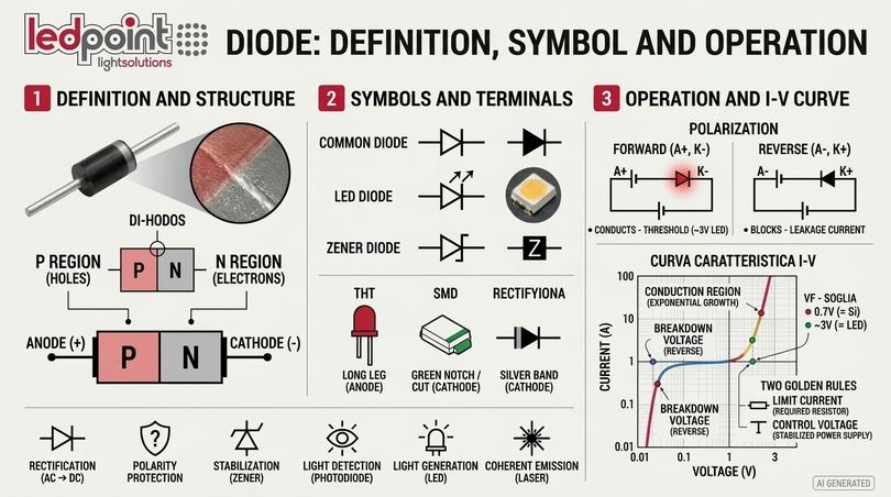
A diode is a two-terminal electronic component that allows current to flow predominantly in one direction. In other words, the diode acts as a one-way valve for electric current: it conducts when the anode is more positive than the cathode by at least a certain voltage (the threshold voltage) and blocks current when the polarity is reversed. The name comes from the Greek "di-hodos", meaning two ways, because the diode indeed has two electrodes.
What is a diode used for? The functions are numerous: rectifying alternating current into direct current (rectifier diode), protecting circuits from polarity reversal, stabilizing a voltage (Zener diode), detecting light (photodiode), generating coherent light (laser diode), and, of course, generating high-efficiency incoherent light: this is the case of the LED diode, acronym for Light Emitting Diode. In a single power supply for LED strips, you will find dozens of diodes of different types, each with a precise task.
Diode in English and technical terminology
Diode in English is simply diode; the LED diode is the Light Emitting Diode, the Zener diode is the Zener diode, the laser diode is the laser diode. In international datasheets you will find recurring acronyms that every professional must know how to read: VF (forward voltage), IF (forward current), VR (reverse voltage), IR (reverse leakage current), Tj (junction temperature), and Rth j-sp (junction-to-solder point thermal resistance).
Diode symbol: how it is represented in an electrical schematic
In an electrical schematic, the diode symbol is a triangle with a bar at the tip. The triangle indicates the anode and the conventional direction of current; the bar indicates the cathode. The LED diode symbol is identical to the common diode, with the addition of two outward-pointing arrows representing light emission. The photodiode, conversely, has two inward-pointing arrows because it absorbs light. The Zener diode has the cathode bar bent into a "Z" or "S" shape.
| Component | Symbol (description) | Typical working direction | Main function |
|---|---|---|---|
| Rectifier diode | Triangle + bar (cathode) | Forward bias | AC/DC conversion, reverse polarity protection |
| LED diode | Triangle + bar + 2 outward arrows | Forward bias | Light emission |
| Zener diode | Triangle + "Z" bar | Reverse bias | Stabilization and overvoltage protection |
| Schottky diode | Triangle + "S" bar | Forward bias | Fast switching, low drop |
| Photodiode | Triangle + bar + 2 inward arrows | Reverse bias | Light detection |
| Laser diode | Triangle + bar + arrows (often with cavity) | Forward bias | Coherent light emission |
Diode anode cathode: which is the positive of the diode?
The positive terminal of the diode is the anode, the negative one is the cathode. To make a diode conduct, the anode must be connected to the positive pole and the cathode to the negative pole of the power supply: this condition is called forward bias. On a cylindrical package rectifier diode, the diode cathode is indicated by a colored band (white, gray, or silver). On a through-hole (THT) LED diode, the cathode is the shorter terminal and corresponds to the flattened side of the base; the anode is the "long leg". On SMD diodes, the cathode is marked by a cut corner, a dot, or a green mark on the package.
What are the terminals of an LED diode called?
The terminals of an LED diode are called anode (A, positive) and cathode (K, negative). The letter K comes from the German Kathode and is used in almost all schematics to avoid confusion with the C for capacitor. On an LED strip, there is no need to identify the anode and cathode of the individual diode: just respect the + and − signs printed on the solder pads, because the printed circuit board already correctly connects all the diodes in series.
2. Diode operation: p-n junction, biasing and characteristic curve
The operation of the diode is based on a phenomenon of semiconductor physics that is identical for a silicon diode costing a few cents and for the highly efficient LED diode of a professional strip. Understanding the p-n junction means understanding why there is a threshold voltage, why the current grows exponentially, and why current control is the golden rule of any LED power supply.
What is a diode in physics: the p-n junction
A diode consists of a p-n junction, which is the union of two regions of semiconductor doped in opposite ways. The p-type region is enriched with "holes" (missing positive charges), the n-type region with free electrons. At the interface between the two zones, a depletion region devoid of free carriers and a potential barrier are formed: it is precisely this barrier that prevents the passage of current until the applied voltage exceeds it. In a silicon diode, the barrier is about 0.6-0.7 V, in a germanium diode about 0.2-0.3 V, and in an LED diode from 1.6 V to over 3 V depending on the material.
Forward bias of the diode
Forward bias of the diode occurs when the anode is connected to the positive and the cathode to the negative. The external voltage reduces the potential barrier; once the threshold voltage is exceeded, electrons and holes cross the junction and the current increases rapidly. How does current pass through the diode? From the anode to the cathode in the conventional direction, while the electrons physically move from the cathode to the anode. When does the diode conduct? Only in forward bias and only above the threshold.
Reverse bias of the diode
In reverse bias (anode to negative, cathode to positive), the barrier widens and only a tiny leakage current flows through the diode, on the order of nanoamperes or microamperes. However, if the reverse voltage exceeds a critical value, called the breakdown voltage, the diode enters reverse conduction with an avalanche or Zener phenomenon. The Zener diode deliberately exploits this region; the LED diode, on the other hand, withstands very low reverse voltages, typically 5 V, which is why an LED diode connected backwards or powered by alternating current without protection can be damaged.
Characteristic curve of the diode
What does the characteristic curve of the diode represent? It is the graph linking the current flowing through the diode to the voltage across its terminals (I-V curve). In forward bias, the curve remains almost flat until the threshold and then rises exponentially according to the Shockley equation: I = IS · (eV/(n·VT) − 1). In reverse bias, the current remains close to zero until breakdown.
The practical consequence is fundamental: small increases in voltage produce large increases in current. In a white LED diode, a variation of just 0.1 V on the forward voltage can vary the current by 20-30%. This is why an LED diode is never powered directly from a voltage source without a limiting element: the LED diode curve is too steep to be controlled by voltage.
| Forward voltage VF (V) | Current IF (mA) | Relative flux (%) | Notes |
|---|---|---|---|
| 2.50 | 0.1 | <1 | Below threshold: diode practically off |
| 2.70 | 2 | 10 | Start of conduction, weak emission |
| 2.85 | 20 | 65 | Working area of medium-power diodes |
| 2.95 | 40 | 100 | Typical nominal working point for 0.2 W 2835 |
| 3.05 | 60 | 140 | Overdriving: efficiency dropping |
| 3.20 | 100 | 190 | High heating, accelerated degradation |
Silicon diode and germanium diode
The silicon diode is the standard of modern electronics: economical, robust, with a threshold voltage of about 0.7 V and very low reverse currents. The germanium diode, historically the first semiconductor used, has a lower threshold (0.2-0.3 V) but higher leakage currents and greater temperature sensitivity; today it remains in use in niches such as weak signal detection. The LED diode uses neither silicon nor germanium as an emissive material, because they are indirect gap semiconductors and do not emit light efficiently: compounds such as gallium arsenide, aluminum-gallium-indium phosphide, and gallium-indium nitride are required.
| Diode type | Material | Typical threshold voltage | Reverse current | Applications |
|---|---|---|---|---|
| Germanium diode | Ge | 0.2-0.3 V | µA | Detectors, crystal radios, historical applications |
| Silicon diode | Si | 0.6-0.7 V | nA | Rectifiers, protections, logic |
| Schottky diode | Metal-Si | 0.2-0.45 V | µA-mA | Switching power supplies, DC-DC converters |
| Red LED diode | AlGaInP | 1.8-2.2 V | <10 µA | Signaling, colored light, monochrome strips |
| Blue / white LED diode | InGaN | 2.7-3.4 V | <10 µA | General lighting, white LED strips |
How a diode behaves in alternating current
In alternating current, a diode conducts only in the half-waves where the anode is positive with respect to the cathode: the result is a pulsating single half-wave current. With four diodes arranged in a bridge (Graetz bridge), full-wave rectification is obtained. This is exactly the principle used in 230 V LED strips and drivers: a high-current AC/DC diode rectifies the mains before powering the LED diodes. An LED diode connected directly to the mains in alternating current without a rectifier and without limitation will be destroyed in a few instants, because the reverse voltage far exceeds the tolerated 5 V.
3. Types of diodes: rectifier, Zener, Schottky, photodiode, laser diode and LED diode
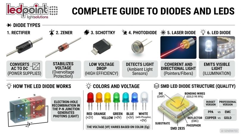
What types of diodes exist? The family is large and each diode is optimized for a specific purpose. For the lighting professional, knowing the main types of diodes is useful because many of them coexist in the same system: the rectifier diode in the power supply, the Zener diode in the protection, the Schottky diode in the converter, the LED diode on the strip. Let's look at the most important ones, grouping the most frequent questions.
Rectifier diode: what is a rectifier used for
The rectifier diode is the "classic" junction diode, designed to withstand high currents and reverse voltages of hundreds or thousands of volts. What is a rectifier diode used for? To convert alternating current into pulsating direct current, which is then smoothed by capacitors and regulated by the power supply electronics. Every 24V power supply for LED strips contains at least one diode bridge, and it is precisely the quality of these components, together with the capacitors, that determines the reliability of the system.
Zener diode: what it is and what it is used for
What is a Zener diode? It is a diode designed to work in reverse bias, in the breakdown region, where it maintains a very stable voltage across its terminals as the current varies. What is the Zener diode used for? To create voltage references, to stabilize small power supplies, and above all to protect circuits from overvoltages. Many power LED diodes integrate a small Zener diode in antiparallel within the package as protection against electrostatic discharges (ESD): this is a construction detail that distinguishes high-end components. The search for "zener led diode" or "zener diode and led" often stems precisely from this combination.
Schottky diode
The Schottky diode uses a metal-semiconductor junction instead of a p-n junction. It has a low voltage drop (0.2-0.45 V) and very fast switching times, which is why it is the preferred diode in high-efficiency switching power supplies and low-voltage reverse polarity protection circuits, where every tenth of a volt lost is energy dissipated as heat.
Photodiode: what are photodiodes used for
The photodiode performs the reverse process of the LED diode: it absorbs photons and generates a current proportional to the incident light. What are photodiodes used for? In twilight sensors, lux meters, infrared remote control receivers, optical barriers, and presence sensors. Many sensors for LED strips work by coupling an emitting diode and a receiving photodiode. Curiously, even a common LED diode can function as a rudimentary light sensor, generating a small voltage when illuminated.
Laser diode: what are laser diodes and difference with LED diode
The laser diode is also a p-n junction that emits light, but the structure includes a resonant optical cavity that produces stimulated emission: the light is coherent, monochromatic, and highly directional. What is a laser diode used for? Optical readers, fiber optic telecommunications, pointers, industrial processing, medical applications such as hair removal. Laser diode vs LED: the LED diode emits incoherent light with a wider spectrum and large emission angle, ideal for illuminating environments; the laser diode concentrates the light into a very thin beam, suitable for pointing, measuring, and transmitting data.
What is the difference between a diode and an LED diode?
This is one of the most searched questions: are diode and LED the same thing? An LED diode is a diode, but not all diodes are LEDs. Both have an anode, a cathode, and conduct in one direction only. The difference between a diode and an LED lies in the material and the purpose: the silicon diode dissipates the recombination energy as heat, the LED diode converts it into photons thanks to direct gap semiconductors. Furthermore, the LED diode has a higher threshold voltage (1.8-3.4 V vs 0.7 V), a much lower maximum reverse voltage (about 5 V vs hundreds of volts), and a transparent package with a lens or phosphor.
| Parameter | Silicon diode (e.g., 1N4007) | White SMD 2835 LED diode |
|---|---|---|
| Function | Rectification, protection | Light emission |
| Material | Silicon | InGaN + YAG phosphors |
| Threshold voltage | ≈0.7 V | ≈2.8-3.2 V |
| Max reverse voltage | 1000 V | ≈5 V |
| Nominal current | 1 A | 60-150 mA (depending on bin) |
| Recombination energy | Heat | Light (photons) + heat |
| Package | Opaque cylindrical | Lead frame with resin and phosphor |
4. LED diode: how it works and what it is made of
Now that the fundamentals of the diode are clear, we can get to the heart of the matter: the LED diode. How does an LED diode work, why does it emit light of a certain color, how is white obtained, what is it made of inside, and why two apparently identical diodes can have completely different performances. This section is the basis for understanding the quality of LED strips.
What is an LED diode: definition and meaning of the acronym
LED stands for Light Emitting Diode: the "D" in LED stands precisely for diode. The LED diode is a p-n junction diode made with direct gap semiconductors that, in forward bias, converts electrical energy into light through electroluminescence. The first visible light (red) LED diode was made in 1962 by Nick Holonyak at General Electric; the high-brightness blue LED diode, which made the white LED diode possible, won the 2014 Nobel Prize in Physics for Akasaki, Amano, and Nakamura.
LED diode operation: why an LED diode emits light
How does the LED diode work? When current flows through the junction, electrons from the n-zone recombine with holes from the p-zone within an active region made of "quantum wells". In each recombination, the electron drops from the conduction band to the valence band and releases energy in the form of a photon. The energy of the photon, and therefore the color of the light, depends on the width of the semiconductor's band gap: according to the relation λ (nm) ≈ 1240 / Eg (eV). A gap of 2.0 eV produces red light around 620 nm, a gap of 2.7 eV produces blue light around 455 nm.
There is therefore a direct link between color and voltage: the shorter the emitted wavelength, the higher the threshold voltage of the LED diode. This is why the red LED diode turns on at about 2 V, while the blue and white LED diodes require about 3 V.
| Color | Wavelength (nm) | Semiconductor material | Typical VF (V) | Applications |
|---|---|---|---|---|
| Infrared (IR) | 850-940 | GaAs, AlGaAs | 1.2-1.6 | Remote controls, video surveillance, sensors |
| Red | 620-630 | AlGaInP | 1.8-2.2 | Signaling, effects, growing |
| Orange / amber | 590-610 | AlGaInP | 1.9-2.2 | Car turn signals, scenic lighting |
| Yellow | 585-595 | AlGaInP | 2.0-2.2 | Signaling, environments with UV filters |
| Green | 520-530 | InGaN | 2.8-3.4 | RGB, signage, architectural |
| Blue | 450-470 | InGaN | 2.8-3.4 | RGB, base for white LEDs |
| White (blue + phosphor) | Continuous spectrum | InGaN + YAG/nitrides | 2.8-3.4 | General lighting |
| Ultraviolet UVA | 365-405 | InGaN | 3.0-3.8 | Polymerization, effects, violet chips |
| Ultraviolet UVC | 260-280 | AlGaN | 5.0-7.0 | Sanitization |
Ledpoint has strips dedicated to almost all these wavelengths: from the infrared LED strip to the ultraviolet / UVC LED strip, from colored light strips to Growing lines for horticulture.
How the white LED diode is obtained
The white LED diode does not exist in nature as a direct emission from a single semiconductor. The most widespread method consists of a blue InGaN chip covered with a layer of phosphors (cerium-doped yttrium-aluminum garnets, nitrides, and silicates) that absorb part of the blue light and re-emit it in yellow, green, and red. The composition and quantity of the phosphor determine the color temperature and the color rendering index of the diode: more red phosphor means warmer light and higher CRI, but also slightly lower efficiency, because every blue→red conversion loses energy (Stokes loss).
There are also "full spectrum" white LED diodes based on violet chips (≈405 nm) with multiple phosphors, which reproduce the sunlight curve with a color rendering index higher than 95. This is the technology of Ledpoint's Sunled and Violet chip lines, designed for museums, galleries, luxury showcases, and environments where color fidelity is a priority.
RGB, RGBW LED diode and bicolour LED diode
What is an RGB LED diode? It is a package containing three chips (red, green, and blue) with separate terminals or in a common anode configuration: by mixing the three intensities with PWM, millions of colors are obtained. The RGBW LED diode adds a fourth white chip to obtain clean whites and pastels; the RGBCCT diode adds two whites (warm and cold). The red-green bicolour LED diode and the tricolor LED diode are variants for signaling. In strips, you will find the RGB diode in RGB LED strips, in RGBW LED strips, and in RGBCCT LED strips.
Addressable LED diode (pixel)
An addressable LED diode integrates, in the same package or next to a group of LEDs, a small integrated circuit (WS2811, WS2812B, WS2814, SK6812, and similar) that receives a digital signal and autonomously regulates the color of its pixel. What is the difference between standard, RGB, and addressable LEDs? In a standard LED, the entire strip has the same color; in an addressable diode, each segment has an independent color, allowing dynamic effects such as scrolling and animations. These are the addressable LED strips (Pixel LED), to be managed with an SPI controller or with Arduino.
What an LED diode is made of: internal structure
What is an LED diode made of? Whether it is a 5 mm LED diode or an SMD diode on a strip, the structure always includes the same elements. Knowing them is essential, because the quality of every single construction element is directly reflected in efficiency, color stability, and lifespan.
| Element | Function | Economy version | Professional version |
|---|---|---|---|
| Semiconductor chip (die) | Generates light in the junction | Small die, second-choice wafer | Adequately sized die, selected wafers |
| Substrate | Epitaxial growth support | Standard sapphire | Patterned sapphire (PSS), better light extraction |
| Bonding wires | Connect the diode chip to the terminals | Copper or copper-silver alloy | 99.99% Gold (Au), adequate diameter |
| Lead frame | Terminals and thermal path | Iron or thin copper | Thick copper with quality silver plating |
| Reflector / cup | Directs light outward | PPA (yellows) | PCT or EMC (heat stable) |
| Phosphor | Converts blue to white | Poorly controlled dosage | Precise dosage, tight binning |
| Encapsulant | Protects and acts as a lens | Epoxy resin | High-stability silicone |
| ESD Zener diode | Protects against electrostatic discharges | Absent | Present in power LEDs |
On the subject of internal connection wires, Ledpoint has published a dedicated in-depth article: 2835 LED wire technology: Au and Ag connections. The gold wire resists oxidation and thermal cycles better, while economical alloys can break after thousands of switch-ons, generating the typical diodes that turn off "randomly" on a strip.
5. Electrical characteristics of the LED diode: voltage, current, polarity
Electrical characteristics are the language with which an LED diode "communicates" with the power supply. Forward voltage, nominal current, maximum current, reverse voltage, and polarity define how the diode must be powered and connected. In this section, we answer the most frequent questions: what voltage does an LED diode have, how many volts are needed to turn it on, how much current it draws, which is the positive.
LED diode voltage: what voltage does an LED diode have and how many volts are needed to turn it on
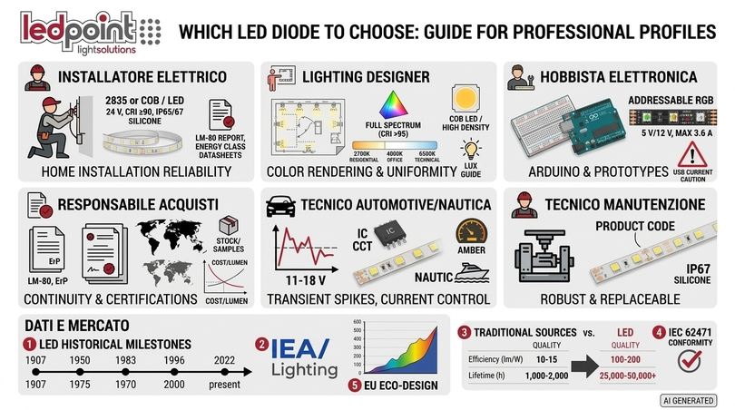
The LED diode voltage, or threshold voltage, is the voltage drop across the diode when the nominal current flows. A single LED diode is not powered "at 12 V" or "at 220 V": it works at about 2 V if red, yellow, or orange, and at about 3 V if blue, green, or white. How many volts for a white LED diode? Between 2.8 and 3.4 V, with a typical value of 3.0-3.1 V. What is the voltage of a high-brightness white LED diode? Similar, but with higher current. Blue LED diode threshold voltage: 2.8-3.3 V. Red LED diode voltage: 1.8-2.2 V. The LED diode voltage also varies with temperature: it drops by about 2 mV for every 1 °C increase in junction temperature.
The expressions "12V LED diode", "220V LED diode", "3 volt LED diode", or "5V LED diode" actually refer to components or modules that already include, in addition to the diode, the limiting electronics: resistors, regulators, or rectifiers. A 12 V strip, for example, connects three diodes in series (3 × 3 V = 9 V) plus a resistor that absorbs the remaining 3 V.
| LED diode | VF min-max (V) | Nominal IF | Maximum continuous IF | Typical power |
|---|---|---|---|---|
| THT 3 mm / 5 mm red | 1.8-2.2 | 20 mA | 30 mA | 0.04 W |
| THT 5 mm ultra-bright white | 2.9-3.4 | 20 mA | 30 mA | 0.06 W |
| THT 10 mm white | 3.0-3.4 | 20-30 mA | 50 mA | 0.1 W |
| SMD 3528 white | 2.9-3.3 | 20 mA | 30 mA | 0.06-0.08 W |
| SMD 5050 (3 chips) | 2.9-3.3 per chip | 3 × 20 mA | 3 × 25 mA | 0.2-0.24 W |
| SMD 2835 medium power | 2.8-3.2 | 60 mA | 150 mA | 0.2-0.5 W |
| SMD 2835 1 W (6 V / 9 V) | 5.6-6.4 / 8.6-9.4 | 100-150 mA | 200 mA | 1 W |
| Power LED 3 W | 3.0-3.6 | 700 mA | 1000 mA | 3 W |
Indicative values from industry datasheets; always consult the specific LED diode datasheet.
LED diode current: how much current does an LED diode draw
How many amperes does an LED diode draw? A traditional 5 mm indicator works at 20 mA (0.02 A); a medium-power SMD 2835 diode between 60 and 150 mA; a 3 W power LED diode up to 700 mA. Current is the parameter that governs the brightness, temperature, and lifespan of the diode: it is the true "knob" of the LED, not the voltage. The maximum LED diode current indicated in the datasheet (absolute maximum rating) should never be considered a working point: exceeding it, even for a few seconds, can irreversibly damage the chip.
How much does an LED diode consume? Consumption is calculated as P = VF × IF. A white diode at 3 V and 20 mA consumes 0.06 W; a 2835 at 3 V and 60 mA consumes 0.18 W. A 120 diode/m strip at 14.4 W/m absorbs on average 0.12 W per diode, including resistors. The milliampere and amperage of an entire strip are instead calculated from the power per meter: I = P / V. A 14.4 W/m strip at 24 V absorbs 0.6 A per meter.
LED diode polarity: how to recognize anode and cathode in an LED
How to understand LED polarity? Here are the practical methods, from the simplest to the most reliable:
| LED diode type | Anode (+) | Cathode (−) |
|---|---|---|
| 3 mm / 5 mm THT LED | Long leg, small internal electrode | Short leg, flat side of the base, large internal electrode |
| SMD 3528 / 2835 LED | Side without marking | Cut corner or notch on the cathode side |
| SMD 5050 LED | Pin opposite to the notch | Pin on the side with the beveled corner |
| Power LED on star | Pad marked "+" | Pad marked "−" |
| LED strip | Pad "+", "V+", "24V" or "12V" | Pad "−", "GND", or color (R, G, B, W) in common anode RGB |
| Any diode | Multimeter in diode test mode: with the red probe on the anode, the diode lights up weakly | |
What happens if I reverse the polarity of the LED?
With reversed polarity, the LED diode simply does not turn on, because it is in reverse bias. The problem arises when the reverse voltage exceeds the limit of about 5 V: the diode can go into breakdown and be damaged. On quality 12 V and 24 V strips, momentary reversal is generally tolerated because the voltage is distributed among multiple diodes in series, but it is still a condition to be avoided. In common anode RGB strips, reversal can cause anomalous lighting; in addressable strips, reversing power and data can destroy the integrated circuit of the first pixel.
LED diode datasheet: how to read it
The LED diode datasheet contains much more information than what is used by someone who buys a strip "by eye". For a specialist, the sections to analyze are: absolute maximum ratings, electro-optical characteristics at 25 °C, binning tables (flux, voltage, chromaticity), relative flux vs current and vs temperature graphs, I-V curve, emission spectrum, radiation diagram (emission angle), thermal resistance, reflow soldering conditions, and LM-80 reliability data.
| Parameter | Unit | What it indicates | Professional reference value |
|---|---|---|---|
| Luminous flux Φv | lm | Total amount of light emitted | Declared per bin at defined current and T |
| Luminous efficiency | lm/W | Light per watt absorbed | ≥180 lm/W on a single mid-power 2835 diode |
| VF | V | Forward voltage | 0.1 V bin for current uniformity |
| CRI (Ra) / R9 | — | Color rendering / saturated red rendering | Ra ≥90, R9 >50 for high-end interiors |
| CCT | K | Color temperature | Binning ≤3 MacAdam steps |
| Emission angle | ° | Beam opening at half intensity | 120° standard SMD, 180° COB |
| Rth j-sp | °C/W | Thermal resistance | The lower it is, the better it dissipates |
| Tj max | °C | Maximum junction temperature | Work at least 30-40 °C below |
| LM-80 / TM-21 | h | Flux maintenance over time | L70 >50,000 h at usage values |
6. How to connect and power an LED diode (12V, 24V, 220V)
How is an LED diode powered? It is perhaps the most searched question absolutely, and the correct answer is only one: by limiting the current. Whether it is turning on an LED diode on a breadboard, powering a 12-volt LED in a car, or designing a 30-meter line of light, the principle does not change. Let's look at the methods, formulas, and schematics, from a single diode up to professional systems.
The principle: the LED diode must be current-driven
As we saw with the characteristic curve, the relationship between voltage and current in a diode is exponential. To safely turn on an LED diode, there must always be an element that establishes the current: a limiting resistor, a constant current regulator, or a dedicated driver. Connecting an LED diode directly to a battery or a power supply without limitation means relying only on the internal resistance of the source: the typical result is an intense flash followed by the burning out of the diode.
LED resistor: how to calculate the resistor of an LED
The formula derives from Ohm's law:
R = (Vsupply − VF × n) / IF
where n is the number of diodes in series. The power dissipated by the resistor is PR = (Vsupply − VF × n) × IF. Then choose the next higher commercial value from the E12 or E24 series, verifying that the nominal power of the resistor is at least double the calculated one.
Example: 12V LED resistor for a white LED diode
Powering a 12V LED: white diode with VF = 3.1 V and IF = 20 mA. R = (12 − 3.1) / 0.020 = 445 Ω → commercial value 470 Ω. Power: 8.9 V × 0.019 A ≈ 0.17 W → 1/2 W resistor for margin. Note that 74% of the energy ends up as heat in the resistor: this is the reason why connecting multiple diodes in series is much more efficient. With three white diodes in series: R = (12 − 9.3) / 0.020 = 135 Ω → 150 Ω, with only 0.05 W dissipated.
| Power supply | Red LED diode (2.0 V) ×1 | White/blue LED diode (3.1 V) ×1 | White LEDs ×3 in series | White LEDs ×6 in series |
|---|---|---|---|---|
| 5 V (USB, Arduino) | 150 Ω | 100 Ω | not possible | not possible |
| 9 V | 360 Ω | 300 Ω | not recommended | not possible |
| 12 V | 510 Ω | 470 Ω | 150 Ω | not possible |
| 13.8-14.4 V (car charging) | 620 Ω | 560 Ω | 270 Ω (constant current IC better) | not possible |
| 24 V | 1.1 kΩ | 1 kΩ | 750 Ω | 270 Ω |
LED diodes in series or parallel
How to connect LED diodes in series? Connect the cathode of the first to the anode of the second, and so on; the current is the same in all diodes and the voltages add up. Series connection guarantees the same current and therefore the same brightness in every diode, but requires sufficient voltage and, if one diode opens, the entire series turns off.
Connecting multiple diodes in parallel with a single common resistor is instead discouraged: due to VF tolerances, the diode with the lower threshold absorbs more current, heats up, further lowers its threshold, and ends up burning out (thermal runaway), dragging the others with it. The professional rule is: series branches with their own resistor or regulator, then branches in parallel. This is exactly the architecture of every LED strip, as we will see in chapter 7.
| Aspect | Series | Parallel with single resistor | Series-parallel (LED strip) |
|---|---|---|---|
| Current in diodes | Identical | Unbalanced | Identical in the branch |
| Luminous uniformity | Excellent | Poor | Excellent |
| Required voltage | High (sum of VF) | Low | 12/24/48 V |
| Open diode failure | Turns off the whole series | Others overload | Turns off only the section |
| Efficiency | High | Low | High |
How to power a 12V LED diode and connect 12V LED diodes
To power a 12V LED diode from a battery or a power supply, the simplest solution is the resistor calculated as above. In a professional context, however, it is better to think in terms of systems: 12V LED strips already contain series of diodes with integrated limitation and must be connected to a stabilized 12V power supply of adequate power (with at least a 20% margin). In battery applications (campers, boats, vans), the actual voltage oscillates between 11 and 14.6 V: in these cases, diodes driven by a simple resistor vary in brightness and can overheat, while strips with current control maintain constant light.
How to turn on an LED diode with 220 Volts
Turning on a 220 V (or 230 V) LED diode necessarily requires a rectifier and a limitation system: a constant current driver, a stabilized low-voltage power supply, or, in high-voltage strips, a bridge rectifier with regulation integrated circuits. "Economical" solutions with a capacitor and resistor in series with the mains produce 100 Hz flicker and do not offer isolation: they are to be avoided in a professional context. Ledpoint offers 230V LED strips with dedicated 230V anti-flicker drivers, which eliminate the typical flicker of direct rectification.
Constant current drivers and constant voltage power supplies
There are two philosophies of LED power supply. The constant voltage (CV) power supply provides stabilized 12, 24, or 48 V: it is the standard for strips, which already contain current limitation. The constant current (CC) driver instead provides a fixed current (350 mA, 700 mA, 1050 mA) allowing the voltage to vary: it is the standard for power LEDs and modules without onboard electronics. A constant voltage strip must never be connected to a constant current driver, and vice versa. You can find both types among Ledpoint power supplies, including constant current power supplies.
LED diode dimming with PWM
How to control the brightness of an LED diode? Reducing the voltage is not a reliable method, because the exponential curve makes the behavior unstable and the tint varies. The standard method is PWM: the diode is turned on and off thousands of times per second, and the perceived brightness depends on the duty cycle. A high PWM frequency (from 2 kHz upwards, better over 20 kHz for video shooting) eliminates perceptible flicker and stroboscopic effects. Monochromatic dimmers, DMX and DALI decoders, and 0/1-10V controllers all work on this principle.
How to correctly connect an LED diode to Arduino
For hobbyists: an Arduino digital pin provides 5 V and a maximum of 20-40 mA. A single LED diode is connected with the anode to the pin via a 220-330 Ω resistor and the cathode to GND. Which resistor to use with a 5-volt LED diode? For a 15 mA red LED diode: (5 − 2) / 0.015 = 200 Ω → 220 Ω; for a white one: (5 − 3.1) / 0.015 ≈ 127 Ω → 150 Ω. To drive a strip, the strip is never connected directly to the pin: a logic-level MOSFET is used or, for addressable strips, the data pin with a 300-470 Ω series resistor and a capacitor on the power supply. 5V LED strips and 5V power supplies are the natural choice for microcontroller projects.
7. The diode in LED strips: SMD, COB packages and circuits
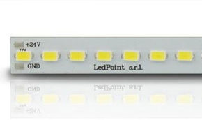
An LED strip is, in essence, a flexible printed circuit on which hundreds of diodes organized in identical sections are mounted. Understanding how the LED strip diode is made, which package is used, and how the circuit is built allows you to correctly read product sheets and compare apparently similar products. In this chapter, we analyze the diode from the point of view of the strip.
Architecture of a strip: sections of diodes in series with limitation
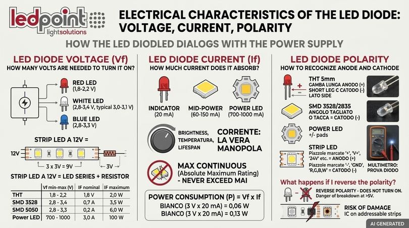
Every LED strip is divided into "sections" or "cutting modules": in each, a group of diodes is connected in series together with a limiting element (resistor or integrated circuit). The sections are then connected in parallel along the two power tracks. The cutting point always corresponds to the end of a section: cutting elsewhere interrupts the series and turns off the diodes in that stretch.
| Strip voltage | White diodes in series (typical) | Drop on diodes | Margin for limitation | Notes |
|---|---|---|---|---|
| 5 V | 1 diode | ≈3 V | ≈2 V | Many cuts, high voltage drops |
| 12 V | 3 diodes | ≈9 V | ≈3 V | Cut every 3 diodes, suitable for battery |
| 24 V | 6-7 diodes | ≈18-21 V | ≈3-6 V | Professional standard |
| 48 V | 14-15 diodes | ≈42-45 V | ≈3-6 V | Long lines, halved current |
| 230 V | Dozens of diodes | Rectified voltage | Regulation IC | Without power supply, with anti-flicker driver |
Diode in resistor-driven or constant current-controlled strips
In standard strips, each series of diodes is limited by a resistor: the current therefore depends on the voltage actually present at that point. If the voltage drops along the strip (voltage drop on the copper), the diodes at the end of the line receive less current and appear less bright. In strips with a constant current control system, however, each section integrates a small integrated circuit that keeps the current in the diodes fixed regardless of voltage variations within a certain range.
The advantages of a constant current-driven diode are three: uniform brightness even on long lines, protection from voltage spikes, and longer lifespan. It is the ideal solution for battery-powered systems, automotive, and marine applications. Ledpoint collects these solutions in the LED strips with constant current control system category, and a concrete example is the 4000K CRI>90 480 led/m 12V 4.8 W/m COB LED strip with current control, which accepts a power supply range from 11 to 18 V while maintaining stable current in every diode, with 480 lm/m and 106 lm/W declared in the catalog.
| Characteristic | Resistor-driven strip | Constant current strip |
|---|---|---|
| Current in diode | Varies with voltage | Stable in the declared range |
| Uniformity on long lines | Drop at the end of the line | Uniform |
| Tolerance to 11-14.6 V batteries | Low | High |
| Overcurrent risk | Present with high voltage | Contained |
| Cost | Lower | Higher |
| Ideal scope | Interiors, short lines, stabilized power supplies | Campers, marine, cars, long lines |
SMD diode: what does SMD mean and how to recognize an SMD LED diode
What does SMD mean? It stands for Surface Mount Device: the diode is soldered directly onto the pads of the printed circuit board without through-holes (SMT technology). The name of the SMD diode indicates its dimensions in tenths of a millimeter: an SMD 2835 diode measures 2.8 × 3.5 mm, an SMD 5050 diode measures 5.0 × 5.0 mm, an SMD 3528 diode measures 3.5 × 2.8 mm. How to recognize an SMD LED diode? By measuring its package and observing the number of chips inside: the 5050 has three visible chips, the 2835 has one only with a large central thermal pad.
| SMD Diode | Dimensions (mm) | Internal chips | Power per diode | Typical efficiency | Strengths | Ledpoint strips |
|---|---|---|---|---|---|---|
| 3528 | 3.5 × 2.8 | 1 | 0.06-0.1 W | Low (dated technology) | Economical, compact | Superseded by 2835 |
| 5050 | 5.0 × 5.0 | 3 | 0.2-0.24 W | Medium | RGB in a single diode | RGB |
| 2835 | 2.8 × 3.5 | 1 | 0.2-1 W | High (up to 150 lm/W on strips) | Excellent dissipation, professional standard | 2835 LED strips |
| 2216 | 2.2 × 1.6 | 1 | 0.1-0.2 W | High | High density, narrow PCBs | 2216 LED strips |
| 3014 | 3.0 × 1.4 | 1 | 0.1 W | Medium | Thin strips | 3014 LED strips |
| 3535 / 3838 / 4040 | 3.5-4.0 | 1-4 | 0.5-2 W | High | High power, RGBW in one diode | 4040, 3838, 3535 |
| 335 side view | 3.5 × 0.8 (side) | 1 | 0.06-0.1 W | Medium | Side emission, backlighting | 335 LED strips |
| 0807 / 1515 / 2016 | 0.8-2.0 | 1 | 0.02-0.1 W | Medium-high | Miniaturization, Neon Flex | 0807, 2016 |
| COB (Chip On Board) | Bare chips on PCB | 320-840 chips/m | Few mW per chip | High | Continuous line without dots, 180° | COB LED strips |
SMD 5050 LED diode and SMD 2835 LED diode: which to choose
The SMD 5050 diode was for years the symbol of LED strips: three chips in a square package, ideal for RGB. For white, however, the SMD 2835 diode has surpassed it on all fronts: at equal power, the 2835 diode offers higher efficiency, better dissipation thanks to the thermal pad, and tighter binning. The 5050 LED characteristics remain advantageous for economical RGB strips and for those looking for 5050 SMD RGB LEDs with three channels in a single diode. For professional white lighting, the current standard is the 2835 diode or COB.
A concrete example of a high-efficiency 2835 diode is the 4000K 3 step 2835 238 led/m 24V 19.2 W/m LED strip: 2600 lm/m, 150 lm/W, 3-step MacAdam binning, and LM-80 compliance declared in the catalog. These are numbers that only a selected diode and a well-dimensioned circuit can achieve.
COB diode: the dot-free line of light
In COB strips, the diode chips are glued directly onto the printed circuit board, without an individual package, and covered with a continuous layer of phosphor and silicone. With 320, 480, 528, or up to 840 chips per meter, the result is a homogeneous line of light, free of the dotted effect, with a 180° emission angle. The COB diode allows for thin profiles and flush diffusers without "dotting", but requires rigorous quality control on phosphor dosage to avoid tint variations along the line. Ledpoint dedicates the COB line and the ≥384 led/m LED strips category to this technology.
Strip voltage and voltage drop
The copper of the tracks has resistance: the longer the strip and the higher the current, the more the voltage drops along the line, and the final diodes receive less current. At equal power, doubling the voltage halves the current and reduces the voltage drop to a quarter (because the lost power is I²R). This is why 24 V strips are the professional standard and 48 V strips allow lines up to 15-20 meters with single-side power supply. Ledpoint explores the topic in the article on 48V LED strips and in the 24V LED strips and 48V LED strips catalogs.
| Voltage | Current per meter | Current on 5 m | Maximum recommended length from one side |
|---|---|---|---|
| 12 V | 1.2 A | 6 A | ≈5 m |
| 24 V | 0.6 A | 3 A | ≈10 m |
| 48 V | 0.3 A | 1.5 A | ≈15-20 m (depending on model) |
8. The diode in LED modules and Neon Flex
The diode does not work only in strips. In LED modules for backlighting and in Neon Flex, the same component is inserted into different construction contexts, with specific optical and thermal requirements. Let's see how the role of the diode changes and what to evaluate in each case.
LED module diode: backlighting for signs and lightboxes
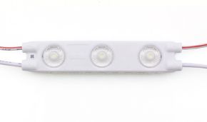
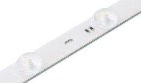
The LED module diode is typically an SMD 2835 or 5730 mounted on a small rigid circuit, often with an optical lens that widens the emission angle up to 160-170°. The modules are connected to each other by a cable in parallel chains and are used to backlight signs, lightboxes, box letters, and lightboxes. In the LED module diode, the lens is decisive: it allows reducing the depth of the box while maintaining uniform illumination, without hot spots on the front panel. You can find this family in Ledpoint LED modules and, for linear surfaces, in backlighting LED bars.
Neon Flex diode: miniaturization and diffusion
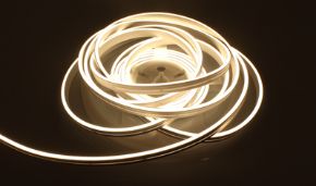
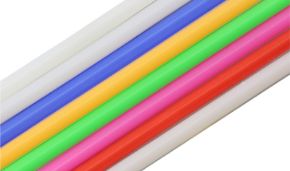
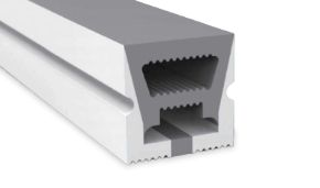
The Neon Flex diode works inside a silicone or PVC profile that diffuses the light uniformly, imitating glass neon without gas, high voltage, and fragility. To obtain a continuous line, very small and very dense diodes are needed: in the new generation Ledpoint Neon Flex, 1515 diodes at 350 led/m on 24 V strips are used, with CRI>90 color rendering. An example is the 3x5mm white 4000K 1515 24V 5.5W 350led/m IP65 Led Neon Flex and the 5x5mm warm white 3000K version. In the Neon Flex diode, density, color uniformity between diodes (binning), and the UV resistance of the diffuser material are crucial.
Explore the complete range in the Neon Flex, 2nd generation Neon Flex, and Neon Flex accessories categories.
9. How to understand the quality of an LED diode: 12 technical criteria
We arrive at the central theme for those who buy and install: how to recognize a quality diode? Two strips with the same power and the same number of LEDs per meter can have very different prices, and the difference almost always lies in the diode and how the diode was mounted. Here are the twelve criteria, in order of importance, that the Ledpoint technical department uses to evaluate an LED diode, with the reference values to distinguish an economical diode from a professional one.
Criterion 1: luminous efficiency of the diode (lm/W)
Luminous efficiency indicates how many lumens the diode produces for every watt absorbed. An efficient diode produces more light and less heat, and heat is the first enemy of lifespan. On the finished strip, which includes resistor and circuit losses, a value higher than 130 lm/W indicates a high-end diode; between 90 and 120 lm/W a good quality diode; below 80 lm/W an economical diode or a system with heavy losses. Attention: ultra-high CRI strips have lower efficiency for physical reasons, so the comparison must be made at equal CRI and CCT.
Criterion 2: color rendering of the diode (CRI, R9, TM-30)
The CRI measures how faithfully the diode reproduces colors compared to a reference source. The Ra value is the average of the first eight pastel samples; the R9 value measures the rendering of saturated red, often neglected by economical diodes. For interior design, retail, food, and museums, the diode must have Ra ≥90 and R9 positive and possibly higher than 50. The TM-30 metric (Rf, Rg) offers an even more complete analysis. Learn more in the Ledpoint article Discovering CRI.
Criterion 3: diode binning and MacAdam steps
During production, each wafer generates diodes with slightly different characteristics. Manufacturers measure them and divide them into "bins" for flux, voltage, and chromaticity. Chromatic binning is expressed in steps of the MacAdam ellipse: a diode with 3-step binning guarantees practically invisible tint differences between one roll and another, while with 5-7 steps the differences are perceptible when placing strips of different batches side by side. For projects with continuous lines, this is a non-negotiable parameter. Also read MacAdam Steps and CCT.
| MacAdam Steps | Color difference between diodes | Recommended use |
|---|---|---|
| 1-2 steps | Imperceptible | Museums, galleries, scientific lighting |
| 3 steps | Barely perceptible in critical conditions | Architectural, retail, hospitality |
| 4-5 steps | Perceptible when placing different batches side by side | Non-critical general lighting |
| >5 steps | Evident | Decorative, economical products |
Criterion 4: brand and origin of the diode chip
The diode is assembled by package manufacturers who purchase or internally produce the chips. Recognized brands publish complete datasheets, curves, LM-80 data, and guarantee supply continuity. A diode without a traceable datasheet is a diode whose long-term behavior cannot be predicted. Ledpoint indicates in the product sheets, when relevant, the manufacturer of the diode, as in the case of the 2700K 3 step LED strip with Honglitronic 2835 diode IP67.
Criterion 5: diode bonding wires
As seen in the structure of the diode, the wires connecting the diode chip to the terminals are a critical point. A diode with gold wires resists oxidation, sulfurization, and thermal cycles better than a diode with copper or copper-silver alloy wires. This data rarely appears in commercial sheets, but it is one of the main indicators of reliability over time.
Criterion 6: lead frame, reflector and sulfur resistance of the diode
The silver-plated lead frame of the diode reflects light outward; if the silver reacts with sulfur compounds present in the air, in some glues, rubbers, or in agricultural and marine environments, it blackens and the diode loses flux and shifts in color. A diode for aggressive environments must have an EMC or PCT reflector and anti-sulfurization protection. Encapsulation materials and silicones used in IP versions must also be compatible.
Criterion 7: diode operating current (derating)
A diode driven at 50-70% of its maximum current lasts much longer and maintains color better. Quality strips use more diodes that are less stressed; economical strips use few diodes pushed to the limit. Comparing two strips with the same power per meter, the one with more diodes per meter (or with larger diodes) generally works at a lower temperature.
Criterion 8: printed circuit board and copper thickness
The PCB is the primary heatsink of every diode and the "electrical line" of the strip. 2 oz (70 µm) copper or higher reduces voltage drop and heating; a wide PCB distributes heat better. An excellent diode on a thin and narrow PCB will run hot and last less than promised by the datasheet.
Criterion 9: stability of current limitation
Precision resistors or constant current integrated circuits ensure that each diode works at the intended point. In economical strips, undersized resistors make the diodes work at currents higher than nominal to "inflate" the declared lumens.
Criterion 10: LM-80 and TM-21 reliability data
The LM-80 test measures the flux maintenance of the diode for at least 6000 hours at different temperatures; the TM-21 method extrapolates the expected lifespan from that data (up to six times the test duration). A diode with an LM-80 report allows declaring values like L70 or L80 in a verifiable way, and it is an increasingly frequent requirement in specifications. Ledpoint marks with a specific icon the strips that mount diodes compliant with the LM-80 standard.
Criterion 11: double-sided tape, IP rating and protective materials
The best diode is useless if the strip detaches from the profile and stops dissipating. Quality 3M double-sided tape (Ledpoint uses 3M 9495LE) guarantees adhesion over time and constant thermal contact. In protected versions, extruded or poured silicone must protect the diode from water, dust, and UV without yellowing. For the meaning of protection ratings, see the IP Code (IEC 60529) standard.
Criterion 12: regulatory compliance and energy labeling
A strip with a quality diode is accompanied by CE marking, RoHS compliance, energy class according to EU Regulation 2019/2015, and, where applicable, photobiological safety declarations (IEC 62471). Ledpoint reports the energy class on every product sheet and explores the topic in the blog tag ErP.
| Criterion | Economical diode | Professional diode | How to verify |
|---|---|---|---|
| Strip efficiency | <80 lm/W | >120-150 lm/W | Technical sheet, integrating sphere |
| CRI / R9 | Ra 80, negative R9 | Ra ≥90, R9 >50 | Spectrometer, photometric report |
| Binning | >5 steps | ≤3 steps | Datasheet, roll comparison |
| Bonding wires | Cu / alloy | Au | Manufacturer declaration |
| Reflector | PPA | PCT / EMC | Diode datasheet |
| Operating current | ≈100% Imax | 50-70% Imax | Calculation W/m ÷ LED/m |
| PCB | 1 oz, narrow | 2 oz or more, wide | Inspection, roll weight |
| Reliability | Not declared | LM-80 / TM-21 | Laboratory report |
| Double-sided tape | Generic | 3M | Liner marking |
| Documentation | Absent | Datasheet, CE, RoHS, ErP | Download from the sheet |
10. Thermal management and diode lifespan
How long does an LED diode last? The answer depends almost entirely on temperature. A diode does not "burn out" like an incandescent bulb: it slowly loses luminous flux and changes color. The speed of this degradation is governed by the junction temperature, and this is why thermal management is the chapter that most separates a durable installation from one that disappoints after a few months.
Diode junction temperature
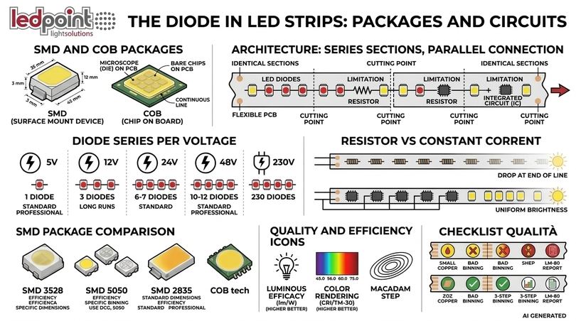
The junction temperature Tj is the temperature of the semiconductor crystal inside the diode. About 50-70% of the energy absorbed by a white diode becomes heat and must be dissipated through the lead frame, the PCB, the double-sided tape, and the support. As a rule of thumb, every 10 °C increase in junction temperature can significantly reduce the useful life of the diode, according to an Arrhenius-type trend. As the temperature increases, the diode also loses efficiency: the flux of a white diode can drop by 10-15% when going from 25 °C to 85 °C junction temperature.
| Diode Tj | Relative flux | VF variation | Estimated L70 lifespan |
|---|---|---|---|
| 25 °C | 100% | 0 mV | Laboratory reference |
| 55 °C | ≈95% | ≈ −60 mV | >50,000 h |
| 85 °C | ≈88% | ≈ −120 mV | ≈30,000-50,000 h |
| 105 °C | ≈83% | ≈ −160 mV | Marked reduction |
| >120 °C | <80% | — | Rapid degradation of phosphor and encapsulant |
Aluminum profiles: the heatsink of the LED strip diode
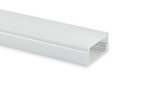
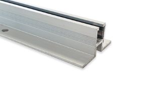
For strips over 9-10 W/m, mounting on an aluminum profile is essential: the profile extends the exchange surface and keeps the diode at temperature. Mounting a high-power strip on wood or plasterboard without a profile is the most common cause of premature diode decay. Adding an opal diffuser also improves uniformity and protects the diodes from dust.
LED diode lifespan: L70, L80, B10, B50
The lifespan of a diode is expressed as the number of hours after which the flux drops to 70% (L70) or 80% (L80) of the initial value; the suffix B indicates the percentage of diodes that may drop below the threshold (B10 = 10%, B50 = 50%). A datum like "L80B10 50,000 h" is much stricter than a generic "50,000 hours", which often corresponds to L70B50 under ideal conditions. According to the US Department of Energy, quality LED products can last up to 25 times longer than incandescent lamps, consuming at least 75% less energy: valid data, however, only if the diode works at the correct temperature.
11. Testing a diode and diagnosing faults
How to understand if a diode works? How to measure an LED diode? For installers and maintenance technicians, knowing how to test a diode is a daily skill. In this section, you will find the procedure with the multimeter, the method for strips, and a table diagnosing the most common diode faults.
How to test a diode with a multimeter
The digital multimeter has a "diode test" function, indicated by the diode symbol, which applies a small current and measures the voltage drop.
- Disconnect power from the circuit and, if possible, isolate the diode to be tested.
- Select the diode test function on the multimeter.
- Red probe on the anode, black on the cathode: a healthy silicon diode shows 0.5-0.7 V; a healthy LED diode shows 1.6-3.2 V and often lights up weakly.
- Reverse the probes: a healthy diode shows "OL" (open circuit).
- Interpret the result: OL in both directions indicates an interrupted diode; a value close to 0 V in both directions indicates a short-circuited diode.
Many economical multimeters supply less than 3 V in diode test and cannot turn on a blue or white LED diode: in that case, the display shows OL even on a healthy diode. A dedicated LED tester or a bench power supply with current limitation set to 5-10 mA can be used.
How to test an LED strip diode
On a strip, the section is tested: a single segment is powered at the nominal voltage and it is observed which diode remains off. If the entire section is off, one of the diodes in the series is interrupted or a solder joint is open. By delicately applying the multimeter probes in diode test mode to the terminals of each diode, the faulty diode will not light up and will show OL. A laboratory trick: temporarily short-circuit the suspected diode with tweezers; if the other diodes in the section turn on, the culprit is identified.
| Symptom | Probable cause | Verification | Solution |
|---|---|---|---|
| LED diode does not turn on | Reversed polarity, interrupted diode, absence of voltage | Measure voltage and diode test | Correct polarity, replace the section |
| One section off | One diode or an open solder joint in the series | Test diode by diode | Replace the section with solder joints |
| Brightness dropping at the end of the line | Voltage drop | Measure voltage start/end | Power from both sides, switch to 24/48 V |
| LED blinks or flickers | Undersized power supply, low-frequency PWM, unstable contact | Check load and connectors | Power supply with 20% margin, quality connectors |
| Diode with dim or reddish light | Partial short circuit in diode, overheating | Thermal camera or careful touch | Mount on profile, replace |
| Diode turning on intermittently | Cracked bonding wire | Heat/cool the diode | Replace the section |
| Color shift over time | Sulfurization, phosphor degradation | Comparison with new sample | Anti-sulfurization diode, better dissipation |
| Strip weakly lit when off | Leakage currents, switch on neutral | Check wiring | Interrupt the positive/phase |
Why do diodes burn out?
The most frequent causes for a diode burning out are: overcurrent (absence of limitation or wrong power supply), overvoltages and mains spikes, polarity reversal with high voltages, electrostatic discharges during handling, overheating due to lack of dissipation, humidity, and corrosion in unprotected versions. In the vast majority of cases, the "burned" diode is the victim of a system error, not an intrinsic defect of the diode. For protection against overvoltages in critical environments, a power supply with integrated protections and, upstream, an SPD device is recommended.
12. Which LED diode to choose: guide by professional profile
Every professional looks at the diode with different eyes: the installer seeks reliability, the designer seeks light quality, the buyer seeks continuity and documentation. In this section, we translate the technical criteria into concrete choices for each profile, linking each need to the most suitable diode and strip.
Electrical installer: reliable diode for domestic installations
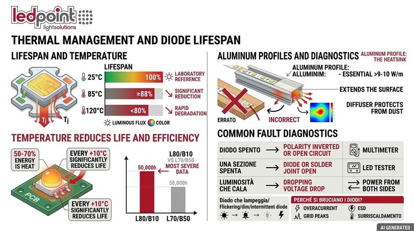
For the installer, the ideal diode is a 2835 or a COB on a 24 V strip, with CRI ≥90, 3-step binning, and a stabilized power supply sized with a 20% margin. The 24 V diode reduces currents, voltage drops, and the risk of connector overheating. For outdoors, IP65-IP67 protected diodes on quality silicone are required. How to verify the quality and lifespan of a diode? Request datasheets, LM-80 reports, and energy class; Ledpoint makes them available in the sheets and catalogs.
Lighting designer: diode for color rendering and uniformity
The lighting designer seeks the diode with the best color rendering and maximum uniformity. For artworks and showcases, the full spectrum diode on a violet chip or Sunled with CRI ≥95 offers the most natural rendering. To choose between warm, neutral, and cool light: 2700-3000 K for hospitality and residential, 3500-4000 K for offices and retail, 5000-6500 K for technical environments. To avoid shadow zones and dotting, a COB diode or a high-density strip in a profile with an opal diffuser is advisable. CCT strips and the Circadian Light line allow varying the color temperature, while for illuminance calculation, the guide how to calculate the lux of an LED installation is useful.
Electronics hobbyist: diode for Arduino and prototypes
For the hobbyist, the most versatile diode is the addressable strip at 5 V or 12 V, which allows controlling every pixel with a few lines of code. For robotics and portable projects, the 5 V diode with USB power supply is the simplest choice. Remember: every addressable RGB diode at full white brightness can absorb up to 60 mA, so 60 diodes absorb up to 3.6 A and require a dedicated power supply, not the PC's USB port.
Industrial purchasing manager: diode with continuity and certifications
For the buyer, the repeatability of the diode over time, documentation (CE, RoHS, LM-80, ErP), stock availability, and the possibility of receiving samples and technical sheets before ordering matter. How to compare price, efficiency, and lifespan? The most honest parameter is the cost per lumen over the useful life: a diode that costs 20% more but lasts twice as long and consumes less is always the most convenient purchase. Ledpoint publishes the stock and availability page and manages customized supplies through the technical department reachable via contacts.
Automotive and marine technician: diode for unstable 12 V
A car's system works at 12.6 V with the engine off and up to 14.4-14.8 V with the alternator charging, with transient spikes even higher. A resistor-driven diode in these conditions works out of specification; a diode driven by a constant current IC with an 11-18 V range maintains stable light and protects the diode from spikes. For dashboards and interiors, low-glare colors (amber, red, warm white) are preferred. For campers and boats, Ledpoint offers the 3000K CRI>90 480 led/m 12V 2.4 W/m LED strip with current control and solutions dedicated to the marine sector.
Industrial maintenance technician: robust and replaceable diode
In environments with dust, humidity, and vibrations, the diode must be IP67 protected with extruded or poured silicone, robust PCB, and soldered connections. Before replacing a diode in a machine, verify: supply voltage, power per meter, color temperature, cutting pitch, PCB width, and IP rating. Noting the product code of the installed strip diode drastically reduces downtime, as it allows reordering the same chromatic bin.
| Profile | Recommended diode | Voltage | Key parameters | Ledpoint category |
|---|---|---|---|---|
| Installer | 2835 / COB diode | 24 V | CRI ≥90, 3 steps, adequate IP | 24V LED strips |
| Lighting designer | Full spectrum / COB diode | 24 V | CRI ≥95, high R9, adjustable CCT | Sunled |
| Hobbyist | Addressable diode | 5 / 12 V | Protocol, pixels/m | Pixel LED |
| Industrial buyer | Diode with LM-80 | 24 / 48 V | Documentation, stock | 48V LED strips |
| Automotive / marine | Constant current diode | 12 V | 11-18 V range | Constant current |
| Maintenance | IP67 diode | 24 V | Silicone, robustness | Outdoor lighting |
13. Data, statistics and the LED diode market
The LED diode is no longer an emerging technology: it is the global standard for lighting. Some data helps to frame the evolution of the diode and the reason why quality, today, matters more than price.
| Year | Milestone |
|---|---|
| 1907 | H. J. Round observes electroluminescence in silicon carbide |
| 1962 | Nick Holonyak creates the first visible light red LED diode |
| 1970s | Green, yellow, and orange LED diodes for signaling |
| 1993 | High-brightness blue LED diode based on gallium nitride |
| 1996 | First blue + phosphor white LED diode |
| 2014 | Nobel Prize in Physics to Akasaki, Amano, and Nakamura for the blue diode |
| Today | Mid-power diode over 200 lm/W in the lab, strips over 150 lm/W in commerce |
According to the International Energy Agency (IEA - Lighting), LED technologies have surpassed half of global lighting product sales, and the complete transition to the LED diode is considered one of the most effective efficiency measures to reduce electricity consumption. In Europe, the Ecodesign Regulation has progressively eliminated halogen and fluorescent lamps: Is it legal to replace halogen lamps with LEDs? Not only is it legal, but it is effectively the only path, because most traditional sources can no longer be placed on the market.
| Source | Typical efficiency (lm/W) | Typical lifespan (h) | Equivalence to 800 lm |
|---|---|---|---|
| Incandescent | 10-15 | 1,000 | 60 W |
| Halogen | 15-25 | 2,000-4,000 | 42-53 W |
| Compact fluorescent | 50-70 | 8,000-10,000 | 13-15 W |
| Quality LED diode | 100-200 | 25,000-50,000+ | 6-9 W |
What is 60 W equivalent to in LED? About 7-9 W with a good quality diode, for about 800 lumens. Are LED lights harmful to health? A quality diode, powered without flicker and with correct shielding, complies with the photobiological safety limits of the IEC 62471 standard; the blue component must be managed with warm color temperatures in evening environments and with optics that avoid direct glare.
14. Top-of-the-range diodes in Ledpoint LED strips
We now apply the twelve criteria to the Ledpoint range. The following table collects some strips that represent the state of the art of the diode in their respective categories, with the technical data declared in the catalog. It is a starting point for choosing the right diode for every project.
| Product | Diode | Catalog data | Why it is top of the range |
|---|---|---|---|
| 4000K 3 step 2835 238 led/m 24V 19.2 W/m LED strip | 2835 | 2600 lm/m, 150 lm/W, Ra>80, LM-80 | High efficiency and 3-step binning: primary lighting |
| 4000K CRI>90 12V COB LED strip with current control | COB 480 chips/m | 480 lm/m, 106 lm/W, 11-18 V range | Diode protected from spikes: campers, boats, off-grid |
| 3000K CRI>90 480 led/m 12V 2.4 W/m LED strip | COB 480 chips/m | 215 lm/m, 98 lm/W, 11-18 V | Warm and stable accent light at low power |
| RGB + CCT 2700-6500K 840 led/m 24V COB LED strip | 5-channel COB | 415 lm/m (2700K), 410 lm/m (6500K) | Dynamic color and white in a continuous line |
| RGB + 3000K COB WS2814 IP65 Pixel LED strip | COB + WS2814 IC | 784 led/m, 14 pixels/m, Ra>90 | Addressable diode with quality white, for outdoors |
| 2700K 3 step 2835 Honglitronic IP67 LED strip | 2835 Honglitronic | 120 led/m, 12 W/m, solid silicone | Branded diode IP67 protected |
| 3x5mm 4000K 1515 IP65 Led Neon Flex | 1515 | 350 led/m, 5.5 W/m, CRI>90 | Miniaturized diode for very thin lines |
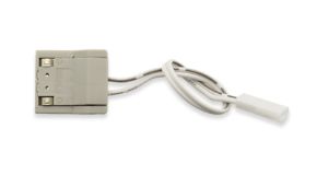
Complete the system with compatible PCB connectors for LED strips, cables, and controllers: an excellent diode expresses its potential only in a system designed with the same care.
Essential diode glossary
A quick glossary to fix the technical terms of the diode encountered in the guide, useful as a reference on site and when reading datasheets.
| Term | Definition |
|---|---|
| Diode anode | Positive terminal of the diode: to make the diode conduct, it must be connected to the positive pole. |
| Diode cathode | Negative terminal of the diode, indicated by the bar in the symbol and by the band or notch on the diode. |
| Diode threshold voltage | Voltage beyond which the diode begins to conduct: 0.7 V for the silicon diode, 1.8-3.4 V for the LED diode. |
| Forward bias of the diode | Condition in which the diode conducts: anode positive with respect to the cathode. |
| Reverse bias of the diode | Condition in which the diode blocks current; beyond breakdown, the diode conducts in reverse. |
| Characteristic curve of the diode | Current-voltage graph of the diode, exponential in forward bias. |
| Zener diode | Diode designed to work in reverse breakdown as a reference or protection. |
| Schottky diode | Metal-semiconductor diode with low drop and fast switching. |
| SMD diode | Surface mount diode, like the 2835 or 5050 diode of strips. |
| COB diode | Diode chips mounted directly on the PCB and covered by continuous phosphor. |
| Diode bin | Selection class of the diode for flux, voltage, and color. |
| Diode junction temperature | Temperature of the diode crystal: the parameter that most influences the lifespan of the diode. |
| Addressable diode | Diode or group of diodes with integrated IC that controls its color pixel by pixel. |
| Rectifier diode | Diode that converts alternating current into direct current, present in every power supply. |
16. FAQ on the LED diode
We collect here the most frequent questions about the diode, the LED diode, and the diode in strips, with synthetic answers designed for quick consultation.
What is a diode and what is it used for?The diode is a semiconductor component with an anode and a cathode that allows current to flow in one direction only. A diode is used to rectify alternating current, protect circuits, stabilize voltages (Zener diode), detect light (photodiode), and emit light (LED diode). Every power supply and every strip contains numerous diodes. |
What is the difference between a diode and an LED diode?The LED is a diode, but made with direct gap semiconductors that emit light. A silicon diode converts recombination energy into heat and has a 0.7 V threshold; the LED diode converts it into light, has a 1.8-3.4 V threshold, and withstands very low reverse voltages, about 5 V. |
Which is the positive of the LED diode?The positive of the LED diode is the anode. In the 5 mm diode, it is the longer leg; the cathode is the short leg, on the flat side of the base. In the SMD diode, the cathode is signaled by a beveled corner or a notch. On strips, just respect the + and − signs on the pads. |
How many volts are needed to turn on an LED diode?A red, yellow, or orange LED diode turns on with about 1.8-2.2 V; a blue, green, or white LED diode requires about 2.8-3.4 V. However, the diode must always be powered with current limitation, because small voltage variations produce large current variations. |
How much current does an LED diode draw?A 3 or 5 mm indicator LED diode draws about 20 mA. A medium-power SMD 2835 diode works between 60 and 150 mA, a 3 W power LED diode up to 700 mA. The operating current of a diode must remain below the maximum value of the datasheet, ideally at 50-70%. |
How to power a 12V LED diode?To power a 12V LED diode, a resistor is inserted in series: R = (12 − VF) / IF. For a 20 mA white diode, about 470 Ω are needed. Alternatively, 12V LED strips are used, which already contain series of diodes with limitation, connected to a stabilized power supply. |
How to turn on an LED diode with 220 Volts?An LED diode is never connected directly to the mains. A constant current driver, a low-voltage power supply, or a 230V strip with integrated rectifier and regulation is required. To eliminate flicker, anti-flicker drivers are used. Capacitor solutions are discouraged because they are not isolated and have flicker. |
How to test an LED diode with a multimeter?Select the diode test function, red probe on the anode and black on the cathode: a healthy LED diode shows 1.6-3.2 V and lights up weakly. Reversing the probes shows OL. OL in both directions indicates an interrupted diode, values close to zero indicate a shorted diode. |
LED diodes in series or parallel: which is better?Series connection guarantees the same current in every diode and is the most efficient. Parallel connection of multiple diodes with a single resistor is discouraged because voltage tolerances unbalance the currents. Strips use branches of diodes in series, each limited, connected in parallel. |
How long does an LED diode last?A quality LED diode, well dissipated, can exceed 50,000 hours before dropping to 70% of the initial flux (L70). The lifespan of the diode depends above all on the junction temperature and the operating current: aluminum profile and correct sizing are decisive. |
Why do LED diodes burn out?A diode burns out due to overcurrent, overvoltages, polarity reversal with high voltage, electrostatic discharges, overheating, or humidity. Almost always the diode is the victim of a system error: unsuitable power supply, absence of dissipation, or incorrect wiring. |
How to understand the quality of a diode in LED strips?Evaluate efficiency (lm/W), CRI and R9, MacAdam binning, diode brand, gold bonding wires, operating current, PCB copper thickness, LM-80 data, double-sided tape, and CE, RoHS, and ErP documentation. A quality diode has a traceable datasheet and verifiable data. |
Better SMD 5050 diode or SMD 2835 diode?For white, the 2835 diode is superior: more efficient, with a thermal pad that dissipates better and tighter binning. The 5050 diode, with three chips in a package, remains useful for RGB strips. For dot-free lines, the best choice is the COB diode. |
What does SMD mean in an LED diode?SMD means Surface Mount Device: the diode is soldered directly onto the surface of the printed circuit board. The numerical code indicates the dimensions of the diode in tenths of a millimeter: 2835 = 2.8 × 3.5 mm, 5050 = 5 × 5 mm, 3528 = 3.5 × 2.8 mm. |
What is the Zener diode used for in LEDs?The Zener diode works in reverse bias and maintains a stable voltage. In power LED diodes, it is often integrated in antiparallel to protect the diode chip from electrostatic discharges. In circuits, it is also used to protect LED diodes from overvoltages. |
Laser diode and LED diode: what is the difference?Both are junction diodes that emit light. The laser diode has a resonant cavity and produces coherent, monochromatic, and directional light; the LED diode emits incoherent light with a wide angle, ideal for illuminating environments, signs, and architectures. |
Can an LED diode be used in alternating current?An LED diode in alternating current would conduct only in the positive half-waves, while in the negative ones it would undergo reverse voltages well above the tolerated 5 V. A rectifier and a limitation system are always required, as in 230 V strips with a dedicated driver. |
Where to buy professional LED diodes and strips?For professional use, it is advisable to buy diodes and strips from specialized suppliers that publish datasheets, energy class, and stock availability. Ledpoint.it offers LED strips, Neon Flex, modules, power supplies, profiles, and controllers with dedicated technical support for installers and designers. |
17. The diode is the heart, the system is the guarantee
We have seen that the diode is a component simple in principle and sophisticated in realization. From the p-n junction to the characteristic curve, from the anode-cathode polarity to current driving, every theoretical concept translates into a practical choice on the LED strip. The quality diode is recognized by efficiency, color rendering, binning, materials, and documentation; but only a coherent system (stabilized power supply, dissipating profile, reliable connections, adequate controller) allows the diode to maintain the promised performance over time.
If you need to choose the right diode for a project, compare the sheets of Ledpoint LED strips, download the datasheets, and, for particular configurations, contact the technical department: every diode you choose today determines the quality of the light for the next ten years. You can also explore the new catalog items and the other in-depth articles of the Ledpoint blog.
This article was developed with the support of artificial intelligence and subsequently reviewed, corrected, and validated by the Ledpoint.it technical team, which guarantees its reliability and compliance with official sources.