






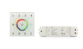
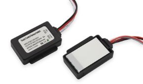
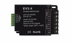
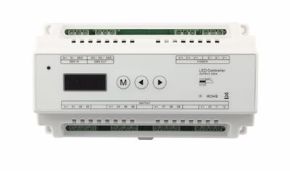
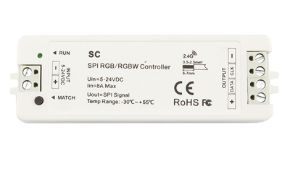
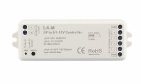
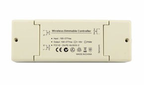
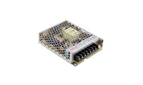
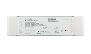
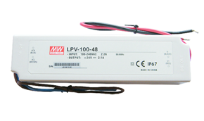
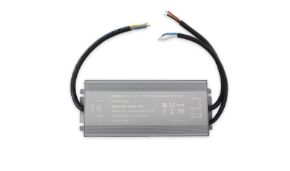
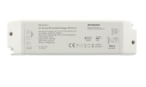
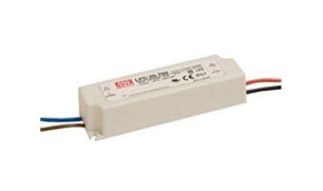





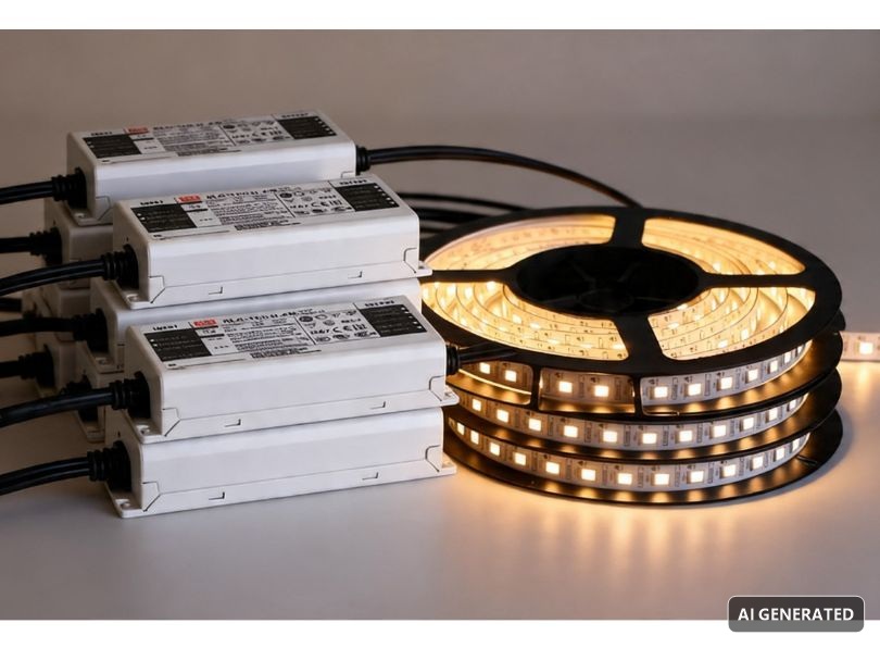
This guide was created after receiving hundreds of questions such as "How do I connect two 12V power supplies in parallel?", "Can I put switching power supplies in parallel?", "How do I power 20 meters of LED strip?". We therefore decided to write the definitive article on parallel power supplies, addressing electrical theory, practical applications, dangers, correct solutions, and errors to avoid.
Whether you are looking to understand how to connect 2 power supplies in parallel for a home project, or you need to design a complex system with parallel LED power supplies over runs tens of meters long, here you will find everything you need: from the definition of parallel connection to the principles of Kirchhoff's laws, from parallel connection wiring diagrams to professional solutions with power repeaters, from power and equivalent resistance calculations to the golden rules for a safe and lasting installation.
In this article...
What is a parallel connection: definition and fundamental principles
Before delving into the specific world of parallel power supplies, it is essential to have a solid understanding of what an parallel connection means in electrical terms. This section constitutes the theoretical foundation on which the rest of the guide rests: without mastering the definition of parallel connection and its fundamental properties, it is impossible to understand why connecting 2 power supplies in parallel presents critical issues and what the correct alternatives are. Let us therefore start from the fundamentals.
Definition of parallel connection
A parallel connection is a circuit configuration in which two or more electrical components share the same connection nodes: their positive terminals are connected together and their negative terminals are connected together. In other words, each component is connected directly to the same voltage source, creating multiple paths for current flow. This is the fundamental definition of a parallel circuit, and it applies equally to resistors, capacitors, lamps, LED strips, and, indeed, power supplies.
To visualize the concept, imagine a main road that splits into multiple parallel lanes before a toll booth: each lane (branch) offers an independent path for cars (the current), but the starting point and endpoint are common. Cars distribute themselves among the lanes based on the "ease of passage" (the resistance), and the total number of cars passing is the sum of the cars on all lanes. This is exactly what happens in an electrical parallel connection: the total current is the sum of the currents in the individual branches, while the voltage across each branch is identical.
When we say that two components are in parallel, we mean that they are subjected to the same potential difference. This is the distinctive feature that separates parallel connection from series connection, where instead the current is the same at every point but the voltages add up. Understanding this difference is crucial for anyone working with parallel power supplies, because it determines the circuit's behavior in terms of current distribution and system stability.
Main characteristics of parallel connection
The fundamental characteristics of a parallel connection can be summarized in four cardinal properties, each of which has direct implications when working with parallel power supplies for LED strips:
- constant voltage on each branch: in a parallel circuit, the voltage is the same across each connected component. If you connect three LED strips in parallel to a 24V power supply, each strip receives exactly 24V (net of cable voltage drops). This property is the main reason why LED strips are connected in parallel and never in series: each strip needs its nominal voltage (12V or 24V) to function correctly. If you connected them in series, a total voltage of 24V × 3 = 72V would be required, well beyond low-voltage safety levels and incompatible with standard power supplies;
- parallel current adds up: the total current supplied by the source (the power supply) equals the sum of the currents flowing in each branch of the parallel circuit. If each LED strip draws 2A, three strips in parallel require 6A. This principle, derived from Kirchhoff's first law (node law), is fundamental for power supply sizing: the power supply must be able to deliver at least the sum of the currents required by all branches, plus a safety margin. When trying to connect two power supplies in parallel, the expectation is precisely to sum the available currents, but we will see that it is not that simple;
- equivalent resistance is lower than the smallest resistance present: in a parallel connection, the total resistance seen by the source is always lower than the smallest resistance among those connected. Adding branches in parallel is equivalent to opening new "roads" for current, reducing the overall resistance of the circuit. This property is expressed by the fundamental formula: 1/Rtot = 1/R1 + 1/R2 + … + 1/Rn. For two equal resistors R in parallel, the total resistance is R/2. For two different resistors, Rtot = (R1 × R2) / (R1 + R2);
- branch independence: a crucial advantage of parallel connection is that each branch operates independently of the others. If a component in one branch fails (the circuit opens), the other branches continue to function normally. This is why household appliances are connected in parallel and not in series: if one light bulb burns out, the others remain lit. The same principle applies to professional LED installations: if one section of LED strip has a problem, the other sections — each with its own power supply — continue to illuminate without interruption.
When we say two elements are in parallel
Two electrical elements are in parallel when they share both connection nodes. More simply, when you connect the positive pole of element A to the positive pole of element B, and simultaneously the negative pole of A to the negative pole of B, the two elements are in parallel. The parallel connection creates a circuit topology in which current has the possibility to choose between multiple paths to go from one node to another.
It is important to distinguish the parallel connection proper from configurations that may seem similar but are not. For example, two LED strips powered by the same wall outlet but with separate power supplies are not in parallel from the DC circuit point of view: each strip has its own independent circuit on the power supply output side. They are in parallel only on the AC mains side, where they share the same domestic power line. This distinction is fundamental when talking about parallel power supplies: the critical issue concerns connecting the DC outputs, not the AC inputs.
To recognize whether a circuit is in series or in parallel, simply follow the current path: if the current is forced to pass through all components one after another (a single path), the connection is in series. If the current has multiple available paths (it splits at nodes), the connection is in parallel. In real circuits, especially in LED lighting installations, mixed series-parallel configurations are often found: individual LEDs on a strip are connected in series-parallel groups, while the strips themselves are connected in parallel to the power supply.
Why parallel connection is the standard in LED lighting
In the professional LED lighting sector, parallel connection is the standard configuration for a very simple practical reason: LED strips operate at fixed voltages, typically 12V or 24V, and must receive exactly that voltage to function correctly. Connecting strips in parallel means that each strip receives the nominal voltage from the power supply, regardless of how many strips are connected. The total absorbed current will be the sum of the currents of the individual strips, and the power supply must be sized accordingly.
24V strips are generally preferred for longer installations because, for the same power, they draw half the current compared to 12V strips, reducing voltage drops on cables and allowing longer runs before needing to introduce a new power injection point. However, even with 24V strips, exceeding 5-10 meters of continuous run requires specific measures, and this is where the need to connect multiple power supplies in parallel, or rather, to find the correct solution for distributing power, comes into play.
Difference between series connection and parallel connection
Fully understanding the difference between series connection and parallel connection is not an academic exercise: it is an indispensable practical skill for anyone working with electrical installations and, in particular, with parallel power supplies for LED strips. This section systematically compares the two types of connection, highlighting the characteristics that make them suitable (or unsuitable) for specific applications in the world of LED lighting.
Series connection: characteristics and behavior
In a series connection, components are connected one after another, forming a single path for current. The output terminal of the first component connects to the input terminal of the second, and so on. The fundamental properties of a series connection are the mirror image of those of parallel connection:
- current is the same at every point in the circuit: since there is only one path, the same current flows through all components. If a component fails and interrupts the circuit, the current drops to zero everywhere: this is the famous effect of old Christmas lights in series, where one burned-out bulb would turn off the entire string.
- voltages add up: the total voltage across the series is the sum of the voltages across each component. If you connect three 10Ω resistors in series and the current is 1A, each resistor has a 10V drop and the total voltage is 30V. For LED strips, this would mean that connecting three 24V strips in series would require a 72V power supply, a dangerous and non-standard voltage. This is why LED strips are never connected in series to each other.
- total resistance is the sum of individual resistances: in a series connection, resistances simply add up: Rtot = R1 + R2 + … + Rn. The total resistance is therefore always greater than the largest resistance present in the circuit. For power supplies in series, this means that voltages add up: two 12V power supplies in series provide 24V, and 2x 12V power supplies in series can power a 24V strip, but this configuration presents other critical issues that we will examine in detail.
Parallel connection: characteristics and behavior (summary)
For comparison, let us summarize the properties of parallel connection already analyzed in the previous section: voltage is the same on all branches, total current is the sum of currents in individual branches; equivalent resistance is lower than the smallest resistance present; branches operate independently. These properties make parallel connection the natural choice for LED lighting, where each strip must receive the same nominal voltage and where branch independence ensures reliability.
Comparison table: series vs parallel
To make the difference between series and parallel even clearer, here is a comparison table summarizing the fundamental properties of the two connection types. This table is a quick reference for electricians, technicians, and designers working with parallel power supplies who need to make informed design decisions.
| Characteristic | Series Connection | Parallel Connection |
|---|---|---|
| Voltage | Divides among components (adds up) | Same on all branches |
| Current | Same at all points | Divides among branches (adds up) |
| Total Resistance | Rtot = R1 + R2 + ... + Rn | 1/Rtot = 1/R1 + 1/R2 + ... + 1/Rn |
| Component failure | Entire circuit interrupts | Only the failed branch stops |
| LED application | Individual LEDs inside a strip (series groups) | LED strips toward the power supply |
| Power supplies | Voltages add up, same current | Same voltage, currents add up |
| Safety | High voltages if many components | Controlled voltage, high currents |
| Household example | Old Christmas lights | Household appliances |
Why household appliances are connected in parallel and not in series
One of the most searched questions in the sector is: why are household appliances connected in parallel and not in series? The answer perfectly illustrates the advantages of parallel connection and applies directly to the world of LED strips.
In a domestic installation, each outlet provides the same mains voltage (230V AC in Italy). By connecting appliances in parallel, each receives the correct voltage to operate, regardless of how many other devices are turned on. If one appliance fails, the others continue to function. The total current drawn from the mains is the sum of the currents of the individual appliances, and the differential circuit breaker is sized to handle this total current.
If appliances were in series, the mains voltage would divide among all devices: with two appliances, each would receive about 115V; with three, about 77V. None would function correctly. Moreover, turning off or failing any appliance would interrupt the circuit for all others. It is exactly the same principle for which LED strips are connected in parallel to the power supply: each strip must receive the full 12V or 24V, and the failure of one strip must not compromise the others.
Mixed configurations: series and parallel in LED lighting
In the practice of professional LED lighting, purely series or purely parallel configurations are rare. Reality is an intelligent combination of the two: series and parallel connections coexist within the same installation, and even within the same LED strip.
Within a single LED strip, LED chips are typically organized in groups connected in series (3 LEDs in series with a current-limiting resistor), and these groups are then connected in parallel with each other along the strip. This series-parallel configuration allows the use of a relatively low voltage (12V or 24V) while having many LEDs on the same strip. The series groups establish the operating voltage of each segment, while the parallel connection of groups allows cutting the strip at marked points without compromising the operation of the remaining groups.
At the installation level, individual strips are connected in parallel to the power supply (or to multiple separate power supplies). If the installation includes dimming, a controller manages the PWM signal, and power repeaters allow expanding the system by connecting multiple sections, always keeping power supplies in parallel on signals but isolated on outputs. This concept of "parallel on signal, isolation on outputs" is the key to professional design of large-scale LED installations.
Fundamental laws: Ohm and Kirchhoff applied to parallel connection
To work with parallel power supplies in a conscious and safe manner, it is essential to master the physical laws that govern the behavior of electrical circuits. In this section we deepen Ohm's law and Kirchhoff's laws in their specific application to parallel connection, with a particular focus on implications for professional LED installations. These principles are not abstract: they are the tools that allow calculating currents, voltages, and resistances in a real installation, and understanding why connecting 2 power supplies in parallel requires specific precautions.
Ohm's law in parallel connection
Ohm's law (V = R × I) is the fundamental relationship between voltage (V), current (I), and resistance (R) in an electrical circuit. In the context of a parallel connection, Ohm's law applies to each branch individually: since voltage is the same on all branches, the current in each branch depends exclusively on the resistance (or impedance) of that branch.
If a 24V power supply is connected to two LED strips in parallel, one with equivalent resistance of 12Ω and the other with equivalent resistance of 24Ω, the current in the first branch will be I1 = 24V / 12Ω = 2A, and the current in the second branch will be I2 = 24V / 24Ω = 1A. The total current supplied by the power supply will be I_tot = 2A + 1A = 3A. This calculation is fundamental for sizing the power supply: it must deliver at least 3A, plus a 30% safety margin, so at least 3.9A are needed, i.e., about 94W at 24V.
When talking about parallel power supplies, Ohm's law also applies to the power supplies' outputs themselves. If two power supplies with slightly different output voltages (e.g., 24.1V and 23.9V) are connected in direct parallel, the 0.2V voltage difference generates a circulating current between the two power supplies, whose value depends on their internal resistance. With very low internal resistances (typical of switching power supplies), this circulating current can be significant and potentially damaging — a concept we will deepen in the dedicated section.
Kirchhoff's first law (node law)
Kirchhoff's first law, also known as the node law or current law, states that the sum of currents entering a node equals the sum of currents leaving the same node. In a parallel circuit, this law translates to the fact that the current supplied by the source (the power supply) splits among the various branches, and the sum of the branch currents equals the total current.
This law is the basis of the principle that parallel current adds up. If we have three parallel branches with currents I1 = 2A, I2 = 1.5A and I3 = 3A, the total current at the node is I_tot = 2 + 1.5 + 3 = 6.5A. For LED installations, this means the power supply must be able to deliver at least 6.5A. If a single power supply does not have this capacity, the solution is not to connect two power supplies in parallel on the same load, but rather to separate the branches into groups each powered by its own dedicated power supply.
The node law is also key to verifying correct current distribution in a parallel connection: by measuring the current in each branch and in the main line with an ammeter (or clamp meter), one can check that the sum of branch currents equals the total current. A significant discrepancy indicates a problem in the circuit — a faulty contact, a malfunctioning LED strip, or a wiring error.
Kirchhoff's second law (loop law)
Kirchhoff's second law, or loop law, states that the algebraic sum of voltages along any closed path (loop) in a circuit is zero. In the context of parallel connection, this law confirms that the voltage across each parallel branch equals the source voltage (minus any voltage drops on connecting cables).
For parallel power supplies, Kirchhoff's second law is crucial for understanding the phenomenon of circulating currents. If two power supplies with different output voltages are connected in parallel, the voltage difference creates an electromotive force that pushes a current to circulate from one power supply to the other through their output terminals. This "parasitic" current does not contribute to powering the load, but generates heat and can damage the power supplies. The loop law allows calculating this current knowing the output voltages and internal resistances of the power supplies.
Practical application: calculating current in a parallel LED strip circuit
Let us see a practical example of how to apply Ohm's and Kirchhoff's laws to size an installation of LED strips connected in parallel. Suppose we want to install four 24V Ledpoint LED strips, each 5 meters long, with a consumption of 14.4W/m.
The load of each strip is: P = 5m × 14.4W/m = 72W. The current of each strip is: I = P / V = 72W / 24V = 3A. By Kirchhoff's first law, the total current required at the node where the four strips are connected in parallel is: I_tot = 3A × 4 = 12A. The total power is: P_tot = 24V × 12A = 288W.
With a 30% safety margin: P_power supply ≥ 288W × 1.3 = 374.4W. Therefore at least 375W of power supply is needed. At this point, the options are: a single 400W power supply (if available and practical), or dividing the load into two groups of two strips each, with two power supplies of at least 190W. This second solution — which is not a true parallel connection of power supplies but a load distribution — is generally preferable for reliability and thermal management.
Calculating resistances, voltages, and currents in a parallel circuit
This section is dedicated to the practice of calculation: formulas, procedures, and tools necessary to design and verify a properly sized parallel circuit. If you are planning an installation with parallel power supplies for LED strips, these calculations are your starting point. We have structured them progressively, from basic formulas to advanced examples, to be useful both to the novice technician and to the engineer seeking a quick reference.
Equivalent resistance in parallel
Calculating equivalent resistance in parallel is one of the fundamental operations of electrotechnics. The general formula for n resistors in parallel is:
1/Rtot = 1/R1 + 1/R2 + 1/R3 + … + 1/Rn
For the common case of two resistors in parallel, the formula simplifies to:
Rtot = (R1 × R2) / (R1 + R2)
And for n equal resistors of value R:
Rtot = R / n
These calculations are essential for sizing parallel power supplies because they allow determining the total load seen by the power supply. Each LED strip can be approximated as an equivalent resistance (the ratio between nominal voltage and absorbed current), and by connecting multiple strips in parallel, the total equivalent resistance decreases, which means total current increases. The power supply must be sized to handle this increased total current.
Calculation examples with Ledpoint LED strips
Consider a 24V LED strip that absorbs 20W/m. For one meter of strip, the equivalent resistance is: R = V² / P = (24V)² / 20W = 28.8Ω. For a 5-meter strip, the equivalent resistance of the single branch is: R_strip = 28.8Ω / 5 = 5.76Ω (linear approximation, valid for strips with single-end power supply on short runs).
If you connect three 5-meter strips in parallel, the total equivalent resistance is: Rtot = 5.76Ω / 3 = 1.92Ω. The total current at 24V is: I_tot = 24V / 1.92Ω = 12.5A. The total power is: P_tot = 24V × 12.5A = 300W. This value confirms the direct calculation: 3 strips × 5m × 20W/m = 300W. Both methods converge, and this is an excellent way to verify calculations.
How to calculate current in a parallel circuit
To calculate current in a parallel circuit, apply Ohm's law to each branch and the node law in sequence to obtain the total current:
- Step 1: identify the voltage across the branches (in parallel it is the same for all).
- Step 2: for each branch, calculate the current: Ii = V / Ri (or, for LEDs, Ii = Pi / V).
- Step 3: sum the currents: I_tot = I1 + I2 + I3 + … + In.
- Step 4: verify that the power supply can deliver at least I_tot × 1.3 (30% safety margin).
This procedure is applicable to any installation with parallel power supplies or with a single power supply powering multiple parallel loads. The key is to be precise in determining the actual consumption of each branch, taking into account the technical specifications of the LED strips used.
How voltage behaves in parallel
In an ideal parallel connection, voltage is identical on all branches. In practice, the actual voltage across each branch may vary slightly due to voltage drops on connecting cables. These drops depend on cable length, conductor cross-section, and flowing current, according to the formula:
ΔV = R_cable × I = (ρ × L) / S × I
where ρ is copper resistivity (0.0175 Ω·mm²/m), L is cable length (outbound + return), S is cross-section in mm², and I is current in amperes.
For installations with parallel power supplies and LED strips, voltage drop is a critical parameter. A voltage difference of even just 0.5V between the start and end of an LED strip can cause visible brightness variations. For long runs, the rule is to keep voltage drop below 3% of nominal voltage (i.e., less than 0.72V for a 24V system). On Ledpoint.it we always recommend verifying cable cross-sections and maximum allowed lengths for each strip type.
Quick calculation table for LED strips in parallel
The following table provides a quick reference for sizing power supplies based on the number of LED strips connected in parallel, assuming 24V strips with different per-meter consumptions and 5-meter runs each.
| Strip consumption (W/m) | 1 strip × 5m | 2 strips × 5m in parallel | 3 strips × 5m in parallel | 4 strips × 5m in parallel |
|---|---|---|---|---|
| 9.6 W/m | 48W → ps 65W | 96W → ps 125W | 144W → ps 190W | 192W → ps 250W |
| 14.4 W/m | 72W → ps 95W | 144W → ps 190W | 216W → ps 280W | 288W → ps 375W |
| 20 W/m | 100W → ps 130W | 200W → ps 260W | 300W → ps 390W | 400W → ps 520W |
| 24 W/m | 120W → ps 156W | 240W → ps 312W | 360W → ps 470W | 480W → ps 624W |
| 40 W/m | 200W → ps 260W | 400W → ps 520W | 600W → ps 780W | 800W → ps 1040W |
Note: power supply values include 30% safety margin. For configurations with more than 2 strips in parallel on the same power supply, consider subdivision into groups with separate power supplies and the use of power repeaters.
Power supplies in parallel: what really happens when you connect the outputs
We arrive at the heart of the matter: what happens if I put two power supplies in parallel? This is the question that generates the most confusion and the most damage in the world of LED installations. The short answer is: it depends on the type of power supply and its internal architecture. But the long answer, the one that is really needed to work safely, requires understanding the internal mechanisms of power supplies and why direct parallel connection of outputs is almost always a bad idea.
The fundamental problem of direct parallel connection
When connecting two power supplies in parallel, i.e., connecting together the positive terminals and together the negative terminals of the outputs, you are essentially connecting two voltage generators in parallel. In theory, if the two power supplies had exactly the same output voltage and the same internal resistance, the current would divide equally between the two and the system would work perfectly. In practice, this never happens.
Every power supply has an output voltage tolerance. A nominally 24V power supply might output 24.1V, another 23.8V. This 0.3V difference, seemingly negligible, generates a circulating current between the two power supplies that is not intended for the load but flows from one power supply to the other. With very low internal resistances (typical of switching power supplies), this current can be high and cause serious problems.
The power supply with slightly higher voltage tends to deliver all the current, while the one with lower voltage does not contribute or even absorbs current from the first. This imbalance causes overload on the dominant power supply, overheating, reduced lifespan, and, in worst cases, sudden failure. The overloaded power supply's protection circuit may intervene, shutting it down and then all the load falls on the other power supply, which may in turn become overloaded. A domino effect is triggered that can lead to complete system failure.
The current sharing function
Some industrial power supplies are specifically designed for parallel connection and integrate a function called "current sharing". This function uses an active balancing circuit that dynamically regulates each power supply's output voltage to ensure uniform current distribution, typically with a maximum imbalance of 5-10%.
Power supplies with current sharing have a dedicated communication bus (often a simple wire between the CS connectors of the various power supplies) that allows them to "negotiate" load sharing. If one power supply delivers more current than the other, the CS bus signals the first to slightly lower its voltage and the second to raise it, until the currents balance.
Warning: the vast majority of standard LED power supplies, including many Mean Well models from the LRS, RSP, and LPV series, do not have the current sharing function and therefore are not suitable for direct parallel connection of outputs. Only certain specific series (such as Mean Well RSP-2000 or DRP-3200) offer this functionality. It is fundamental to verify the power supply datasheet before attempting any parallel connection.
Blocking diodes: a partial solution
A solution often cited for safely connecting power supplies in parallel is the use of blocking diodes (also called "OR diodes" or "decoupling diodes") on each power supply's output. The diode prevents current from flowing "backward" from one power supply to another, eliminating the problem of circulating currents.
The connection with parallel power supplies and diodes works as follows: the positive terminal of each power supply is connected to the anode of a diode, the diodes' cathodes are connected together and connected to the load. In this way, current can flow only from the power supply to the load, never from one power supply to another. If one power supply has a slightly higher voltage, it initially delivers more current, but as the load increases, its voltage drops until it matches the other power supply's voltage, which then begins to contribute.
However, this solution presents significant disadvantages: each diode introduces a voltage drop of about 0.5-0.7V (for silicon diodes) or 0.2-0.3V (for Schottky diodes). On a 24V system, a 0.5V drop represents 2% of the voltage, not negligible for LED strips, where even small voltage variations affect brightness. Moreover, diodes dissipate power as heat (P = V_diode × I), and for high currents (10A and above) this dissipation requires power diodes with adequate heatsinks. For professional LED installations, blocking diodes for parallel power supplies are an acceptable solution only for small systems or as redundancy.
Connecting two 12V power supplies in parallel: practical case
The search "connecting two 12V power supplies in parallel" is one of the most frequent in the sector. The typical scenario is: you have an LED project that requires more current than a single 12V power supply can provide, and you want to "double" the power by connecting a second identical power supply in parallel.
As we have seen, direct connection of outputs is risky without the current sharing function. The correct solution is:
Option A: divide the load. Assign to each 12V power supply an independent portion of the load. If you have 10 meters of LED strip, the first power supply powers the first 5 meters and the second the last 5 meters. The two power supplies are not connected in parallel; each has its own independent circuit. If synchronization is needed (dimming), a power repeater is used.
Option B: use Schottky diodes. If for space or wiring reasons a single power injection point is necessary, the two 12V power supplies can be connected in parallel with Schottky diodes on each output. The actual voltage at the load will be about 11.7V (12V – 0.3V diode drop), and the LED strips must be compatible with this reduced voltage. This solution is less efficient and less recommended than Option A.
Option C: switch to 24V. If the project allows, use 24V LED strips with a single adequately sized power supply. The 24V strips available on Ledpoint.it offer significant advantages in terms of maximum run length and lower current for the same power, often making the need to connect power supplies in parallel superfluous.
Switching power supplies: operation, safety, and ripple
Switching power supplies are the beating heart of any LED lighting installation. Understanding how they work, why they are the standard choice for LED strips, and what their characteristics relevant to parallel connection are is fundamental for designing safe and high-performance installations. In this section we answer the most frequent questions about switching power supplies, from operating principle to the issue of ripple, from safety to technical specifications to evaluate when choosing.
How a switching power supply works
A switching power supply (or switch-mode power supply) converts the AC mains voltage (230V AC, 50Hz in Italy) into a stabilized DC voltage (typically 5V, 12V, 24V, or 48V DC) through a high-frequency conversion process. Unlike old linear power supplies, which used large 50Hz transformers, switching power supplies operate at much higher frequencies (typically from 50kHz to several MHz), which allows using much smaller and lighter transformers, with higher efficiencies.
The conversion process in a switching power supply follows four main phases. First, the AC mains voltage is rectified and filtered to obtain a raw DC voltage (about 320V DC from rectifying 230V AC). This voltage is then "chopped" (commutated, switching) at high frequency by a MOSFET or IGBT transistor, creating a high-frequency square wave. The square wave passes through a small high-frequency transformer that reduces it to the desired voltage. Finally, the output is rectified, filtered, and regulated by a feedback circuit that keeps the output voltage constant regardless of load and mains voltage variations.
Are switching power supplies safe?
Yes, switching power supplies are safe, provided they are of quality, certified, and correctly installed. A good switching power supply for LEDs integrates multiple protections:
- Overload protection (OLP): the power supply reduces power or shuts down if the load exceeds the nominal limit. This protects both the power supply and the load (the LED strips) from damage caused by a short circuit or incorrect sizing. Overload protection is particularly important when working with parallel power supplies, because a load imbalance could overload one of the power supplies;
- Short circuit protection (SCP): in case of output short circuit, the power supply shuts down immediately or enters "hiccup" mode (intermittent restart attempts). This protection prevents catastrophic damage and fire risks;
- Over-temperature protection (OTP): an internal sensor monitors the power supply temperature and shuts it down if it exceeds the safe limit. This protection is essential for power supplies installed in enclosed or poorly ventilated spaces;
- Over-voltage protection (OVP): if the output voltage exceeds a certain limit (typically 110-130% of nominal voltage), the power supply shuts down. This protection is important to safeguard LED strips from excessive voltages that could damage them or reduce their lifespan;
- Galvanic isolation: the high-frequency transformer provides electrical isolation between the 230V AC mains and the low-voltage DC output. This isolation is fundamental for user and operator safety. The best switching power supplies for LEDs offer at least 3kV isolation between input and output.
To ensure maximum safety, it is fundamental to choose CE-certified switching power supplies and preferably with recognized quality marks such as UL, TÜV, or CB.
What is ripple in power supplies
Ripple is the residual oscillation of a switching power supply's output voltage, superimposed on the nominal DC value. It is an alternating (AC) component of relatively small amplitude compared to the DC voltage, but which can have important effects on LED strips. Ripple is measured in millivolts peak-to-peak (mVpp) and its frequency is typically twice the power supply's switching frequency.
High ripple can cause flickering in LED strips, especially if the ripple frequency is low enough to be perceived by the human eye or a phone camera. This flickering can be annoying, cause visual fatigue, and, in work environments, compromise lighting quality. For professional LED applications, ripple must be below 150mVpp at full load.
Quality power supplies, such as Mean Well models, keep ripple well below this limit thanks to carefully sized output filters. When connecting power supplies in parallel, the ripple of the two outputs can interfere, creating beating phenomena that amplify the oscillation. This is a further reason why direct parallel connection of outputs is not recommended.
Constant voltage vs constant current power supply
In the LED world there are two fundamental types of power supply: constant voltage (CV) power supplies and constant current (CC) power supplies. The distinction is crucial because it directly influences connection methods, including parallel connection.
Constant voltage (CV) power supplies provide a constant output voltage (12V, 24V, 48V) and let the current vary based on the load. They are used for LED strips, which integrate current-limiting resistors to regulate current in each LED group. LED strips are designed to operate at constant voltage and are connected in parallel to the CV power supply output.
Constant current (CC) power supplies provide a constant output current (350mA, 700mA, 1050mA) and let the voltage vary based on the load. They are used for LED modules and some "constant current" type strips that do not have integrated resistors. LED modules powered by constant current are connected in series, not in parallel, because the same current must flow through all modules.
When talking about parallel power supplies in the context of LED strips, we are almost always referring to CV (constant voltage) power supplies. Parallel connection of CC power supplies is a different and even more critical operation, because connecting current generators in series or in parallel requires specific expertise and additional components.
What is a dual power supply for
A dual power supply is a power supply with two separate outputs, usually symmetrical (e.g., +12V and -12V relative to a common reference). In the field of LED lighting, dual power supplies are not common; they are more typical of signal electronics (audio preamplifiers, analog circuits). However, the concept of "power supply with multiple outputs" is relevant for those seeking to avoid connecting power supplies in parallel: a power supply with two independent outputs can power two separate sections of LED strips without the risks of direct parallel connection, while occupying a single chassis.
Difference between transformer and power supply
A very common confusion in the LED sector concerns the difference between transformer and power supply. Many installers, especially those with a background in halogen lighting, call "transformer" what is actually a switching power supply. This confusion is not only terminological: it has important practical implications, especially when it comes to connecting parallel power supplies. Let us clarify once and for all the distinction.
What is a transformer
A transformer is a purely passive device that converts an alternating voltage (AC) into another alternating voltage, higher or lower, without converting the type of current. A 230V/12V transformer, for example, takes the 230V AC from the mains and reduces it to 12V AC. The output is still alternating current, with the same frequency as the mains (50Hz). Transformers were widely used for 12V halogen lamps, where alternating current was perfectly adequate.
A transformer is not suitable for LED strips, because LEDs operate on direct current (DC) and require a stabilized voltage. Connecting an LED strip to a transformer produces unpredictable results: 50Hz flickering (perceptible as annoying flicker), possible damage to LEDs due to the sinusoidal wave's peak voltage (the peak value of 12V AC is about 17V, well beyond the maximum voltage of 12V DC strips), and absence of any regulation or protection.
What is a power supply (for LEDs)
An LED power supply (typically a switching power supply) converts the AC mains voltage (230V AC) into a stabilized DC voltage (12V DC, 24V DC, etc.). The process includes rectification (AC to DC conversion), filtering (elimination of oscillations), regulation (maintaining constant voltage as load varies), and protection (overload, short circuit, over-temperature).
The power supply is the only correct choice for LED strips. It is also the only device for which it makes sense to discuss parallel connection: connecting transformers in series or in parallel is a completely different operation, with different rules, and has no application in the LED world. If someone asks you to "connect two LED transformers", in most cases they mean "connect two LED power supplies in parallel" and the answer, as we have seen, is that direct parallel connection is almost always to be avoided.
Table: transformer vs power supply
| Characteristic | Transformer | Switching power supply |
|---|---|---|
| Input | AC (230V, 50Hz) | AC (230V, 50Hz) |
| Output | AC (reduced voltage) | Stabilized DC |
| Voltage regulation | No (varies with load) | Yes (stable as load varies) |
| Protections | None or minimal | OVP, OCP, SCP, OTP |
| Efficiency | 80-90% | 85-95% |
| Weight and size | Large and heavy | Compact and lightweight |
| Suitable for LEDs | No | Yes |
| Parallel connection | Not applicable for LEDs | Only with current sharing or specific solutions |
LED power supplies in parallel: the limit of direct parallel connection
In the context of professional LED lighting, connecting multiple power supplies is common practice for managing high loads or very long runs of LED strips. However, it is fundamental to distinguish between parallel connection of power supply outputs (often discouraged) and power stratification via controllers and repeaters (the correct professional solution). This section deepens the specific topic of parallel LED power supplies, analyzing technical limits and alternatives.
Why LED power supplies are not designed for direct parallel connection
According to technical specifications from major manufacturers, such as Mean Well, the vast majority of LED power supplies, including the LPC, LPV, HLG series and many others, do not have the "current sharing" function and therefore are not suitable for direct parallel connection of outputs to increase available power. Brutally connecting the output terminals of two different (or even identical) power supplies in parallel could cause load imbalances, circulating currents, and damage to internal components of the power supplies.
The technical reason is simple: LED power supplies are optimized to deliver a constant voltage to a load ranging from zero to maximum nominal. The internal regulation circuit uses voltage feedback that keeps the output at the set value (e.g., 24.0V) regardless of load. When connecting two power supplies in parallel, the two regulation circuits compete: each tries to impose its own output voltage, and inevitable differences (even fractions of a volt) generate instability, oscillations, and parasitic currents.
To meet high power requirements, the correct solution consists in dividing the LED load into independent subsections, each powered by its own dedicated power supply. This architecture, which is not a true parallel connection of power supplies but an intelligent power distribution — offers advantages in terms of safety, reliability, thermal management, and ease of maintenance.
When direct parallel connection is allowed
There are specific situations in which connecting power supplies in parallel is allowed and safe. These cases require power supplies explicitly designed for parallel operation:
- Power supplies with active current sharing: some Mean Well industrial series (e.g., RSP-2000, DRP-3200, RCP-2000) and from other manufacturers (Siemens SITOP, Phoenix Contact QUINT) offer the current sharing function for parallel connection. These power supplies, often defined as parallel SITOP power supplies or similar, have a dedicated CS (Current Share) bus that allows balancing currents between units connected in parallel. The maximum number of units connectable in parallel is specified in the datasheet (typically 2-4 units).
- Power supplies with N+1 redundancy function: in critical applications (telecommunications, industrial automation, emergency lighting), configurations with redundant power supplies are used where N units provide the necessary power and +1 unit is on standby. In case of failure of one unit, the standby unit automatically takes over. This configuration requires specific power supplies with integrated decoupling diodes or external redundancy modules.
- ATX power supplies in parallel (PC domain): the search "parallel ATX power supplies" or "parallel PC power supplies" is common among modding and overclocking enthusiasts. In the PC domain, connecting two ATX power supplies requires the use of a specific adapter (dual PSU adapter) that synchronizes the turning on of the two power supplies and, typically, connects them on separate rails (not in true parallel). This application is very different from the LED world and should not be confused with connecting LED power supplies in parallel.
The risk of parallel DC power supplies without protection
Connecting DC power supplies in parallel without any protection (neither current sharing, nor decoupling diodes) is the most risky situation. The main problems are:
- Circulating current: as explained in previous sections, the voltage difference between the two power supplies generates a current that circulates from the power supply with higher voltage to the one with lower voltage, without passing through the load. This current causes overheating and can trigger overload protections.
- Oscillations: the regulation circuits of the two power supplies can enter oscillation, alternately trying to raise and lower the output voltage. These oscillations translate into amplified ripple on the output voltage, with consequent flickering of LED strips and possible damage to LED chips due to transient overvoltage.
- Cascading failure: if one power supply fails with output shorted (a not uncommon failure mode in switching power supplies), the other power supply suddenly finds itself having to power both the original load and the short circuit of the failed power supply. The result is a catastrophic overload that can damage even the second power supply and the load.
All these risks are eliminated by adopting the correct solution: load distribution on independent power supplies with synchronization via power repeater, as we will see in the next section.
The professional solution: Skydance power repeater
Here is the solution that elegantly solves the problem of how to connect power supplies in parallel for large-scale LED installations: Skydance power repeaters. This technology represents the professional standard for expanding the power of an LED installation without the risks of direct parallel connection of power supply outputs. Let us see how it works, why it is superior to any other solution, and how to configure it in your project.
How a power repeater works
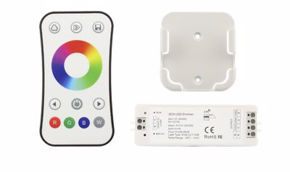
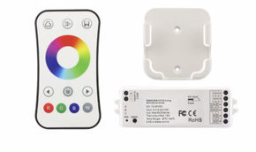
A power repeater is a device that receives the PWM (Pulse Width Modulation) signal from the main controller and replicates it on a new section of LED strip, using a separate power supply. The principle is simple but brilliant: instead of connecting two power supplies in parallel on the same output, the system is separated into independent sections that share only the control signal.
Operation in detail: the main controller (e.g., a single-channel dimmer, an RGB controller, or an RGBW controller) is powered by the first power supply and manages the first section of LED strip. The controller output, which is a low-power PWM signal, is connected to the input of the Power Repeater. The repeater analyzes the incoming PWM signal and faithfully reproduces it at the output, driving the second section of LED strip with power supplied by the second power supply. The result: the two sections of strip behave as a single strip — same brightness, same color temperature, same dimming — but are powered by separate and independent power supplies.
This architecture is the professional answer to the question "how to connect two power supplies in parallel": you do not connect the power supply outputs in parallel, but you connect the control signals in parallel via power repeaters. The power supplies remain electrically isolated on their outputs, eliminating all risks of direct parallel connection.
Skydance power repeaters: characteristics and models
The Skydance power repeaters available represent the state of the art in expansion technology for LED installations. Here are the main models and their characteristics:
Skydance EV1 series (single-channel)
The Skydance EV1 is a single-channel repeater designed for monochromatic and tunable white LED strips. Main characteristics: output up to 8A (192W at 24V), compatibility with PWM signals from 100Hz to 50kHz, ultra-compact dimensions, DIN rail or screw mounting. The EV1 is the ideal solution for expanding an installation with power supplies in parallel on the signal without compromising output isolation.
Skydance EV1-X (single-channel high current)
The Skydance EV1-X is the high-current version of the EV1, with output up to 30A (720W at 24V). This model includes 3kV photoelectric isolation between input and output, ensuring that any faults on one power supply do not propagate to the entire system. The EV1-X is designed for the most demanding installations, where the power involved is high and safety is a priority.
Skydance EV2 and EV4 series (multi-channel)
The repeaters EV2 (2 channels) and EV4 (4 channels) are designed for RGB, RGBW, and multi-channel LED strips. Each channel has its own power output, allowing faithful replication of all colors and shades from the main controller. The EV4, with 4 channels of 5A each (total 20A, 480W at 24V), is the standard choice for large-scale scenic RGB installations.
Unlimited expansion
Skydance repeaters (such as the EV1, EV2, or EV4 series) can be connected in parallel to the control signal to expand the output in a practically unlimited way. The main controller's PWM signal is distributed to all repeaters, each of which drives its own strip section with its own power supply. There is no theoretical limit to the number of connectable repeaters — in practice, installations with 10-20 repeaters and as many power supplies are common in hotels, shopping centers, and large-scale architectural installations.
Galvanic isolation: the extra safety
One of the most important advantages of Skydance Power Repeaters compared to direct connection of power supplies in parallel is galvanic isolation. Many models, such as the EV1-X, offer 3kV photoelectric isolation between input (control signal) and output (power to LED strips). This isolation guarantees that: any faults on a power supply (overvoltage, short circuit) do not propagate to other sections of the installation. Each section is an independent electrical island, and a problem on one section does not compromise the others.
Ground currents and electromagnetic disturbances do not circulate between sections, improving PWM signal quality and reducing the risk of flickering or luminous artifacts.
The installation is more safe for operators during maintenance, because one can work on one section without risks deriving from other powered sections.
Wiring diagram with power repeater
Here is the typical wiring diagram for an LED installation with separate power supplies and Skydance power repeater
| Component | Function | Connection |
|---|---|---|
| Power supply 1 | Powers controller + strip section 1 | AC→DC, output to controller |
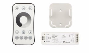
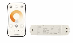
| Controller (e.g., Skydance V1-L) | Dimming, effects, PWM management | Input: power supply 1. Output: strip section 1 + PWM signal to repeaters |
| Power Repeater 1 (e.g., EV1) | Replicates PWM signal on section 2 | Signal: from controller. Power: power supply 2. Output: strip section 2 |
| Power supply 2 | Powers repeater 1 + strip section 2 | AC→DC, output to repeater 1 |
| Power Repeater 2 (e.g., EV1) | Replicates PWM signal on section 3 | Signal: from controller. Power: power supply 3. Output: strip section 3 |
| Power supply 3 | Powers repeater 2 + strip section 3 | AC→DC, output to repeater 2 |
In this configuration, the three power supplies work in parallel on the signal (all receive the same PWM command via the controller), but remain electrically isolated on the outputs to the LEDs. It is the professional solution to the problem of how to connect power supplies in parallel: achieving the desired effect (more power, longer runs, synchronization) without the risks of direct parallel connection.
Parallel connection wiring diagram for LED strips: step-by-step guide
After having understood the theory, risks, and solutions, it is time to see the complete operating procedure. This section provides a step-by-step guide for realizing an LED installation with multiple power supplies and correct parallel connection wiring diagram.
Step 1: define total load
The first step for any installation with parallel power supplies (or, better, with distributed power supplies) is total load calculation. Proceed as follows:
Identify the LED strip you intend to use and find the per-meter power (W/m) in the technical specifications of each product. Multiply the per-meter power by the total installation length: P_total = W/m × length (m). Add the 30% safety margin: P_power supply = P_total × 1.3. This is the minimum power value that your power supplies, collectively, must provide.
Step 2: divide the load into sections
Instead of seeking a single gigantic power supply or attempting to connect power supplies in parallel on the same load, divide the installation into sections. The guiding rules are:
- maximum length per section: depends on the LED strip used. For high-power strips (>15W/m), the practical limit is 5 meters per power injection point. For low-to-medium power strips (<10W/m), one can reach 7-10 meters.
- power injection points: each section must have its own power injection point, preferably at the center of the run to minimize voltage drop (bi-end power supply) or at the beginning (single-end power supply).
- power per section: calculate the power needed for each section and choose a power supply with nominal power 30% higher (safety margin).
Step 3: choose power supplies and controller
For each section, select the appropriate power supply. The selection criteria are: output voltage corresponding to the strip (12V or 24V), nominal power 30% higher than the section load, safety certifications (CE, UL), IP protection rating adequate to the installation environment (IP20 for dry interiors, IP67 for outdoors or humid environments).
For the first section, choose a Skydance controller compatible with the strip type (single-channel for monochromatic strips, multi-channel for RGB/RGBW). For subsequent sections, choose a Skydance power repeater of the appropriate series.
Step 4: wire the system
Follow the parallel connection wiring diagram described in section 9.4. Critical wiring points: use cables of adequate cross-section for the current (minimum 1mm² for 6A, 1.5mm² for 10A, 2.5mm² for 16A in DC). Keep DC cables as short as possible to reduce voltage drops. Connect the PWM signal from the controller to all repeaters with shielded cable if distances exceed 10 meters. Verify that all connections are secure and protected (screw terminals, quick connectors, tinned ferrules).
Step 5: test and verify
Before considering the installation complete, perform the following tests to verify that the parallel connection of signals and distributed power supply work correctly:
- voltage test: measure the voltage across each LED strip section with a multimeter. Voltage must be within ±5% of nominal voltage (e.g., 22.8V-25.2V for a 24V system). Significant differences between sections indicate voltage drop problems or uncalibrated power supplies;
- current test: measure the current absorbed by each section with a clamp meter. The value must correspond to the calculated load (±10%). Anomalous currents may indicate short circuits, defective strips, or wiring errors;
- synchronization test: dim the controller from 100% to 10% and verify that all sections follow the dimming uniformly, without visible delays or differences. If multiple controllers or dimmable drivers connected to the same wall button are used, they can be synchronized with a long press (>10 seconds), bringing all devices to 100% brightness simultaneously;
- thermal test: after one hour of operation at full load, verify the temperature of power supplies and repeaters. Temperatures above 60°C indicate the need to improve ventilation or reduce load.
Practical examples with LED strips
Theory is fundamental, but practice is what counts in the field. In this section we present two concrete examples of real installations, demonstrating how to manage power without resorting to direct connection of power supplies in parallel. These examples are representative of the most common situations that electricians and designers face.
Example 1: 15-meter run of high-power strip
Suppose we want to install 15 meters of Ledpoint Performance F52-40s-120822 strip (24W/m at 24V) in a commercial corridor. This is a high-density strip, ideal for accent lighting with high color rendering.
Total load: 15m × 24W/m = 360W.
With a 30% safety margin, at least 468W of power supply is needed. A single 500W power supply might suffice, but powering 15 continuous meters of high-power strip from a single point would cause unacceptable voltage drop (the LEDs at the end of the strip would be visibly less bright). The professional solution is subdivision into sections.
Suggested configuration: divide the strip into three 5-meter sections, powered by three separate power supplies.
- Section 1 (0-5m): powered by a 150W power supply via the main controller (e.g., Skydance V1-L). The controller manages dimming and sends the PWM signal to the repeaters.
- Section 2 (5-10m): managed by a Skydance EV1 repeater (8A max, 192W at 24V), powered by its own dedicated 150W power supply. The repeater receives the PWM signal from the controller and replicates it on the second section.
- Section 3 (10-15m): managed by a second Skydance EV1 repeater, also powered by a dedicated 150W power supply.
In this configuration, each power supply manages only 120W of actual load (5m × 24W/m), well below the 150W nominal capacity. The margin is ample, voltage drop is minimal on each 5-meter section, and the system is easily maintainable (one section can be disconnected without affecting the others). The three power supplies work in parallel on signals (all synchronized by the controller) but are completely isolated on DC outputs.
Example 2: scenic installation with ultra-high-power COB strip
For a 10-meter scenic installation using the Ledpoint COB F52-300-1600OR2 strip (40W/m), the load is decidedly high: 10m × 40W/m = 400W.
- Configuration with high-current EV1-X repeater: in this case, one can exploit the high capacity of the Skydance EV1-X repeater, which supports up to 30A (720W at 24V).
- Section 1 (0-5m): powered by a 260W power supply via the main controller. Load: 200W.
- Section 2 (5-10m): managed by the EV1-X repeater, powered by its own 260W power supply. Load: 200W. The EV1-X, with its 30A capacity and 3kV photoelectric isolation, guarantees that the two power supplies work in parallel on the signal but remain electrically isolated on the outputs to the LEDs.
This configuration demonstrates how it is possible to manage significant loads (400W and above) without ever connecting the outputs of power supplies in direct parallel, maintaining safety, reliability, and perfect synchronization.
Summary table of examples
| Parameter | Example 1 (15m) | Example 2 (10m) |
|---|---|---|
| LED Strip | Performance F52-40s-120822 | COB F52-300-1600OR2 |
| Power per meter | 24W/m | 40W/m |
| Voltage | 24V | 24V |
| Total load | 360W | 400W |
| Number of power supplies | 3 × 150W | 2 × 260W |
| Repeater | 2 × Skydance EV1 | 1 × Skydance EV1-X |
| Direct output parallel | No | No |
| Synchronization | Yes, via PWM | Yes, via PWM with 3kV isolation |
Advantages and disadvantages of parallel connection
Having explored the theory, practice, and professional solutions for parallel power supplies, it is time to make an objective balance of the advantages and disadvantages of parallel connection applied to LED lighting. This analysis is useful for designers who must justify design choices and for technicians who must evaluate alternatives.
Advantages of parallel connection
Uniform voltage on each load: the main advantage of parallel connection for LED strips is that each section receives the correct nominal voltage. There are no voltage divisions as in series connection, and each strip operates under optimal conditions. This translates into uniform brightness and maximum LED lifespan.
Branch independence and reliability: in a parallel circuit, failure of one branch does not compromise the others. If a section of LED strip fails or must be disconnected for maintenance, the other sections continue to function. This advantage is fundamental in commercial and industrial installations, where continuous lighting is an operational requirement.
Easy expansion: adding new LED strip sections to an installation with parallel connection is simple: just add a new power supply and a new power repeater. It is not necessary to redesign the entire system, which reduces costs and intervention times. The applications of parallel connection in LED lighting make the most of this modularity.
Low-voltage safety: parallel connection keeps the system voltage at the nominal level (12V or 24V), well below the danger threshold (50V DC according to CEI EN 50178 standard). This makes parallel LED installations intrinsically safe from the point of view of electrical risk to people.
Better thermal management: by distributing the load over multiple power supplies via parallel connection, each power supply manages only a fraction of the total power. This reduces heat generated by each single power supply, improving efficiency and lifespan of the entire system.
Disadvantages and challenges of parallel connection
High total currents: in a parallel connection, total current is the sum of currents of individual branches. For large-scale installations, currents can reach tens of amperes, requiring adequately sized cables and components rated for these currents. The cost of copper for power cables can significantly impact the project budget.
Wiring complexity: compared to a system with a single power supply, an installation with multiple parallel power supplies (distributed) requires more cables, more connections, and more attention in wiring design. Complexity increases with the number of sections and with the need to manage both power cables and signal cables for power repeaters.
Risk of short circuit on single branch: if a branch of the parallel circuit goes short circuit, the current on that branch increases enormously, potentially overloading the power supply or distribution cable. For this reason it is important to provide fuses or automatic circuit breakers on each branch, especially in large-scale installations.
Need for balancing: to ensure uniform brightness in all sections, it is necessary that the voltage across each LED strip section be as equal as possible. Voltage drops on cables, power supply tolerances, and resistance differences between strips can create visible imbalances. Careful wiring design and use of quality power supplies minimize this problem.
Table: advantages vs disadvantages
| Advantages | Disadvantages |
|---|---|
| Uniform voltage on each load | Potentially high total currents |
| Branch independence (reliability) | Wiring complexity |
| Easy expansion | More components to manage |
| Low-voltage safety | Larger cable cross-sections for currents |
| Better distributed thermal management | Need for voltage balancing |
| Selective maintenance per section | Higher cost (more power supplies and repeaters) |
Power supplies in series or parallel: when to use what for LED strips
One of the most frequent questions among professionals working with LED lighting is: power supplies in series or parallel? The answer is not univocal and depends on the specific situation, but for LED strips the choice is almost always parallel, with due precautions. Let us see in detail when each configuration makes sense.
When to use parallel connection (distributed)
Parallel connection (i.e., separate power supplies for independent sections, with signal synchronization) is the correct choice in the vast majority of LED installations: installations with constant-voltage LED strips (12V or 24V), practically all commercial LED strips. Installations that are long and require more than one power injection point to avoid excessive voltage drops. Installations with need for synchronized dimming on multiple sections. Projects where reliability is a priority (commercial, hospitality, architectural). Any situation where total load exceeds the capacity of a single reasonably sized power supply.
When to use series connection
Connecting power supplies in series is much less common in the LED world, but has its specific applications: connecting two power supplies in series to sum voltages: for example, 2x 12V power supplies in series to obtain 24V. This configuration is theoretically possible and safe, provided the two power supplies are of the same brand and model, have the same nominal current, and the outputs are in series (positive of first to negative of second). However, in practice it is always preferable to use a single 24V power supply: simpler, more reliable, more economical.
Series connection is instead standard for constant-current LED modules, where modules are connected in series and driven by a constant-current power supply (CC driver) that maintains constant current regardless of the number of connected modules. This is however a different architecture from the theme of parallel power supplies for LED strips.
Decision table: series or parallel?
| Scenario | Recommended connection | Reasoning |
|---|---|---|
| Long monochromatic LED strips | Parallel (distributed) | Constant voltage, independent sections |
| Scenic RGB LED strips | Parallel (distributed with multi-channel repeater) | Color synchronization on multiple sections |
| Need 24V from 12V power supplies | Series (but better a single 24V power supply) | Sum of voltages |
| Constant-current LED modules | Series | Constant-current architecture |
| Redundancy for reliability | Parallel with diodes/current sharing | Service continuity |
How to increase DC voltage and amperage in an LED installation
Two questions closely related to the theme of parallel power supplies are: "how to increase DC voltage" and "how can I increase the amperage of a power supply". These questions reflect real needs of professionals and deserve clear and operational answers.
How to increase DC voltage
To increase DC voltage in an LED system, the options are:
- use a power supply with the desired output voltage: the simplest and safest solution. If you need 24V and have a 12V power supply, do not try to double the voltage: buy a 24V power supply.
- connect power supplies in series: as seen in the previous section, connecting 2x 12V power supplies in series produces 24V. This is a valid option only if you have no alternatives, and requires power supplies with isolated outputs (floating output), a condition satisfied by most quality switching power supplies.
- use a DC-DC boost converter: a boost (step-up) converter takes a DC voltage and increases it to a higher value. For example, it can convert 12V to 24V or 48V. These devices have their own power and efficiency limitations, and for professional LED installations they are not generally the preferred choice compared to using a power supply of the correct voltage.
How to increase amperage
It is not possible to increase the amperage of a single power supply beyond its nominal specifications. The maximum output current is determined by the power supply's internal architecture and exceeding it leads to overload and intervention of protections (or, worse, failure).
To obtain more current (more amperage) at a given voltage, the options are:
- Use a higher-power power supply. If you need 15A at 24V (360W), choose a power supply of at least 470W (with 30% margin). High-power power supplies reach 750W per single unit.
- Distribute the load over multiple power supplies (the solution with power repeater described in this guide). This is the correct strategy for managing loads that exceed the capacity of a single power supply, and is preferable to attempting to connect power supplies in parallel directly.
- Use power supplies with current sharing. As seen in section 5.2, some industrial power supplies are designed for parallel operation with active current sharing. In this case, connecting 2 or more units in parallel actually increases available amperage. This option is valid only with power supplies specifically designed for this purpose.
Series connection: when it is needed and how to implement it
Although this guide is focused on parallel power supplies, it is important to also treat series connection for completeness and to answer the numerous related questions. Series connection has its applications in the LED world, and understanding it helps to choose consciously between series and parallel.
How to make a series connection
In a series connection, components are connected one after another: the positive terminal (output) of the first connects to the negative terminal (input) of the second, and so on. Current flows through all components in sequence. To connect two power supplies in series, connect the positive terminal of the first power supply to the negative terminal of the second; the total voltage will be the sum of the voltages of the two power supplies, and the maximum current will be that of the power supply with the lower nominal current.
To join two power supplies in series safely, it is fundamental to verify that both power supplies have isolated outputs (floating outputs), i.e., that the outputs are not referenced to ground. Most switching power supplies have isolated outputs, but it is always advisable to verify the datasheet. Power supplies with ground-referenced output (e.g., power supplies with case connected to negative) cannot be put in series without modifications, because a short circuit would be created.
Applications of series connection in the LED world
Series connection in the LED world has two main applications: driving constant-current LEDs/modules (where modules are in series and the current power supply regulates voltage to maintain constant current) and combining power supplies to obtain higher voltages (e.g., 2x 12V power supplies in series for 24V). Both applications are less common compared to parallel connection for LED strips, but have their place in specific projects.
Voltage generators in parallel and current generators in series
To complete the theoretical framework of parallel power supplies, it is useful to analyze the behavior of ideal and real generators in parallel and series configurations. This section is particularly useful for engineers and designers who want to understand the theoretical foundations of the problems encountered in practice.
Voltage generators in parallel
An ideal voltage generator maintains a constant voltage at its terminals regardless of delivered current, with zero internal resistance. Connecting ideal voltage generators in parallel with different voltages is a physical contradiction: Kirchhoff's loop law would be violated, because the voltage difference between the two generators cannot exist without a resistance on which to manifest. The result is a theoretically infinite circulating current, a short circuit.
In reality, switching power supplies are almost-ideal voltage generators but with very low internal resistance (typically 10-100mΩ). When you connect two power supplies in parallel with slightly different voltages, the circulating current is limited by the sum of internal resistances, but can still be significant: a 0.2V difference with total internal resistances of 50mΩ generates a circulating current of 4A, current that does not contribute to powering the load but generates heat and stress on components.
Current generators in series
Symmetrically, connecting current generators in series with different currents is problematic: Kirchhoff's node law would be violated. In practice, constant-current LED drivers are almost-ideal current generators, and connecting them in series requires that all have the same nominal current. Series connection of CC drivers is used to control very long chains of LEDs in series, where total voltage exceeds the capacity of a single driver.
The parallel with parallel power supplies is evident: just as connecting current generators with different currents in series is problematic, connecting voltage generators with different voltages in parallel is equally problematic. The solution is always the same: use generators specifically designed for combined operation (current sharing for parallel, voltage sharing for series) or separate the loads so that each generator operates independently.
Practical applications of parallel connection in lighting
Parallel connection is omnipresent in the world of lighting, not only LED, but also in traditional installations. This section explores the most common applications, from domestic installations to large commercial realizations.
Parallel connection in domestic installation
In a home electrical installation, all lamps are connected in parallel to the 230V AC mains. Each light bulb receives the same mains voltage and absorbs its own current. If one bulb burns out, the others remain lit. When replacing traditional lighting with LED strips, the logic remains the same: each LED light point has its own power supply (or shares a power supply with other light points connected in parallel to the same DC output). For most domestic applications (coves, under-cabinets, accent lighting), a single power supply for each zone is sufficient, and parallel connection is simple and direct.
Commercial and architectural lighting
In commercial and architectural installations, the dimensions and powers involved make necessary the use of multiple parallel power supplies (distributed). A hotel with corridors illuminated by LED strips for tens of meters, a restaurant with atmospheric lighting around the entire perimeter, a shop with illuminated showcases and shelves: in all these cases, the solution is load distribution on separate power supplies with synchronization via power repeater.
The modularity of the system allows designing scalable installations: one starts with the necessary sections and adds new sections over time, without having to redesign the installation from scratch. This is the true practical advantage of parallel connection in professional lighting.
Outdoor installations and IP67
For outdoor installations (building facades, gardens, pools, signs), the choice of power supplies and components must take into account the IP protection rating. Power supplies with IP67 rating are sealed and water-resistant, ideal for outdoor installations. Even in these contexts, parallel connection via power repeater is the standard choice, with the care to use waterproof connections and cables with weather-resistant sheaths.
Parallel connection of UPS and backup systems
A variant of the "parallel power supplies" theme concerns connecting UPS (uninterruptible power supplies) in parallel to increase capacity or redundancy. The principle is similar to that of power supplies: connecting UPS in parallel requires units specifically designed for parallel operation, with communication buses for load balancing and switching management. This application is more typical of data centers and critical infrastructures than of the LED world, but the underlying principle (the need for current sharing and synchronization) is the same.
Safety and regulations for parallel power supplies
Safety is a non-negotiable aspect when working with parallel power supplies or with any power supply configuration for LED strips. This section summarizes applicable regulations, safety best practices, and certifications to request. It is particularly important for electricians and technicians who must ensure installation compliance with current regulations.
Reference regulations
The main regulations to respect for LED installations with parallel power supplies in Italy are: CEI EN 61347, control devices for lamps (safety requirements for LED power supplies), CEI EN 62031 (LED modules for general lighting, safety requirements), CEI EN 60598 (luminaires — general requirements), CEI 64-8 (electrical installations for use at nominal voltage not exceeding 1000V AC and 1500V DC), and Low Voltage Directive 2014/35/EU.
For installations with parallel power supplies (distributed), it is fundamental to respect electrical safety requirements relating to SELV (Safety Extra Low Voltage): maximum voltage 50V DC or 25V AC. LED strips at 12V and 24V fall into this category, which significantly simplifies installation requirements compared to mains-voltage systems.
Mandatory protections
Each power supply in an installation with parallel connection must be equipped with the following protections: overload protection (OLP), short circuit protection (SCP), over-temperature protection (OTP), and galvanic isolation between AC input and DC output.
At the installation level, it is advisable to provide: a differential circuit breaker (RCD/GFCI) on the AC circuit powering the power supplies, fuses or miniature circuit breakers on the AC side sized for total current, and possibly a fuse on the DC side for each LED strip section (especially for high-power installations).
Power supply certifications
To guarantee the safety of parallel power supplies, it is fundamental to use certified products. The main certifications to look for are: CE (European conformity, mandatory), UL/cUL (American/Canadian certification, index of superior quality), TÜV (German certification body, guarantee of reliability), CB (international certification scheme), and ENEC (European quality mark for electrical components).
Mean Well products, widely available, are CE, UL, TÜV, and CB certified, and represent a globally recognized safety standard in the LED power supply sector.
Common errors in connecting power supplies in parallel
After years of technical support, we have collected a significant case history of errors committed during the connection of parallel power supplies. This section lists the most common ones, explains the consequences, and provides the correct solution for each. Knowing these errors in advance can save you time, money, and burned components.
Error 1: direct output connection without current sharing
The most serious and most common error is connecting the outputs of two power supplies in parallel without the current sharing function. As extensively explained in this guide, this connection causes circulating currents, load imbalances, and potential damage to power supplies. Solution: separate the loads and use power repeaters.
Error 2: power supplies with different voltages in parallel
Connecting power supplies in parallel with different nominal voltages (e.g., a 12V and a 24V) is a catastrophic error: the 12V voltage difference generates enormous currents that destroy both power supplies and can damage the load. Solution: always use power supplies of the same nominal voltage, and verify with a multimeter the actual output voltage before connection.
Error 3: undersized cables
In a parallel connection, total current can be very high. Using cables of insufficient cross-section causes excessive voltage drops, cable overheating, and fire risk. Solution: calculate maximum current and choose cable cross-section according to regulatory tables (CEI-UNEL 35024/1).
Error 4: no safety margin on power
Sizing the power supply exactly to the load power (e.g., 100W power supply for a 100W load) means working at 100% capacity, with overheating, reduced lifespan, and risk of overload protection intervention. Solution: always provide a 30% margin (130W power supply for a 100W load).
Error 5: not considering voltage drop
For long LED strip runs, voltage drop on cables can be significant. LEDs at the end of the strip receive less voltage and appear less bright, with a visible effect especially in white strips. Solution: reduce DC cable length, increase wire cross-section, or introduce new power injection points (with additional power supplies and power repeater).
Error 6: reversing polarities
Reversing positive and negative cables in a parallel connection creates a direct short circuit between the power supply and the branch with reversed polarity. Switching power supplies with short circuit protection shut down immediately, but those without protection can be irreversibly damaged. Solution: always verify polarity with a multimeter before connecting cables, and use polarized connectors where possible.
Error 7: ignoring power supply ventilation
Switching power supplies, especially high-power ones, generate significant heat. Installing them in enclosed spaces without ventilation causes overheating and intervention of thermal protection (OTP). In installations with multiple parallel power supplies, the heat generated by each power supply adds up, worsening the problem. Solution: ensure adequate ventilation, respecting minimum distances indicated in the power supply datasheet (typically 30-50mm on all sides) and providing natural or forced convection.
Golden rules for professional installation
We condense in this section the golden rules for a professional LED installation with multiple power supplies. These rules derive from our practical experience and manufacturer guidelines, and are applicable to any project with parallel power supplies (distributed) for LED strips.
Safety margin
Always choose power supplies with a nominal power 30% higher than actual need. This margin increases power supply reliability, reduces overheating, extends useful life (a power supply working at 70% of its capacity can last over 10 years), and guarantees stable operation even under non-optimal mains voltage conditions.
Uniform voltage
If using multiple power supplies for the same line (but on different sections), ensure that the voltage difference is minimal (ideally <0.2V) to avoid visible brightness variations between sections. To adjust output voltage, many Mean Well power supplies have a trimmer (Vadj) that allows varying output voltage by ±10%. Adjust all power supplies to the same actual voltage before installation.
Voltage drop
For long runs, reduce DC cable length or increase wire cross-section to prevent LEDs at the end of the strip from appearing less bright. Total voltage drop on cables should be less than 3% of nominal voltage: less than 0.36V for 12V systems, less than 0.72V for 24V systems. For runs longer than 5 meters of cable, consider using cables of at least 2.5mm².
Push synchronization
If using multiple dimmable controllers or drivers connected to the same wall button, they can be synchronized with a long press (>10 seconds), bringing all devices to 100% brightness simultaneously. This function, available on many Skydance controllers, guarantees that after an initial synchronization all channels respond uniformly to button commands, without visible delays or differences between sections.
Cable protection
All DC cables must be mechanically protected with conduit, corrugated sheath, or rigid tubing, especially in wall or ceiling installations. Power cables (from the DC side of the power supply to LED strips) must be separated from signal cables (from controller to power repeaters) to avoid electromagnetic interference that could cause flickering.
Installation documentation
For every installation with parallel power supplies (distributed), it is good practice to draw up an electrical diagram indicating: the position of each power supply, the power and voltage of each, the repeaters and controllers with their connections, the length and cross-section of cables, and the power of each LED strip section. This documentation facilitates future maintenance and troubleshooting.
Tools and testing procedures for parallel circuits
To verify that a parallel circuit with multiple power supplies functions correctly, adequate tools and systematic testing procedures are needed. This section is a practical guide for electricians and technicians who want to ensure correct installation of their LED installations.
Necessary tools
Digital multimeter: indispensable tool for measuring DC voltages (verification of power supply output voltage and voltage across LED strips), DC currents (verification of current absorbed by each section), and resistances (verification of cable and connection continuity). A good multimeter with ±0.5% precision is sufficient for most verifications.
DC clamp meter: allows measuring current in a cable without disconnecting it, by inserting the cable into the clamp's "jaw". It is particularly useful for verifying current distribution in a parallel circuit with multiple branches, without interrupting installation operation.
Infrared thermometer: allows measuring surface temperature of power supplies, power repeaters, and LED strips without physical contact. Useful for identifying anomalous overheating that could indicate sizing or ventilation problems.
Oscilloscope (optional): for measuring output voltage ripple and verifying PWM signal quality at power repeaters. Not necessary for standard installations, but useful for diagnosing flickering or interference problems in complex installations.
Recommended testing procedure
Before power-on: verification of polarity of all connections with multimeter. Verification of cable continuity with resistance test. Visual check of all connectors and terminals.
Power-on and no-load test: turn on one power supply at a time, verifying output voltage before connecting load. Compare output voltages of power supplies: they should differ by less than 0.2V.
Load test: connect LED strips section by section, verifying current and voltage at each step. Verify that sum of branch currents corresponds to total current (Kirchhoff's first law).
Full operation test: dim from 100% to 0% and verify uniformity. Verify synchronization between sections. Measure temperatures after one hour of operation at full load.
Market data and trends in the LED power supply sector
To contextualize the theme of parallel power supplies in the broader panorama of the LED lighting market, we present some significant data and trends that influence professionals' choices in the sector.
Growth of the LED power supply market
According to sector analyses, the global market for LED drivers and power supplies is in constant growth, with an estimated compound annual growth rate (CAGR) around 15-18% in the period 2023-2030. This growth is driven by the expansion of LED lighting in all sectors (residential, commercial, industrial, automotive, and architectural) and by growing demand for intelligent control systems (smart lighting) that require increasingly sophisticated power supplies and controllers.
| Segment | Market share 2024 (estimate) | Growth forecast to 2028 |
|---|---|---|
| CV power supplies for LED strips | 35% | +20% CAGR |
| CC drivers for LED modules | 30% | +15% CAGR |
| Dimmable power supplies | 20% | +25% CAGR |
| Smart/IoT power supplies | 10% | +35% CAGR |
| Power supplies for special applications | 5% | +12% CAGR |
Technological trends
The main trends in the LED power supply sector, relevant for those working with parallel power supplies, include: increased efficiency (goal >95% for new generations), size reduction (miniaturization), integration of digital communication protocols (DALI-2, Bluetooth, Zigbee, WiFi) for smart control, compliance with increasingly stringent regulations on energy efficiency (ErP Lot 29) and electromagnetic compatibility (EMC), and development of power supplies with integrated current sharing functionalities to simplify parallel connection in large-scale installations.
Technical insights on parallel connection
In this technical deep-dive section, we explore advanced aspects of parallel connection that interest in particular electronic engineers, installation designers, and specialized technicians. These topics complete the framework provided in previous sections and answer the most technical questions received from Ledpoint.it users regarding parallel power supplies. We have decided to dedicate an entire section to these aspects because, in our experience, it is precisely the technical details that make the difference between a mediocre installation and an excellent installation.
Detailed analysis of stability of circuits with parallel power supplies
The stability of a system with parallel power supplies depends on multiple factors that interact with each other in complex ways. To fully understand the dynamics at play, it is necessary to analyze the behavior of switching power supplies from the point of view of automatic control theory. Each switching power supply has a feedback loop that monitors output voltage and compares it with an internal reference, accordingly regulating the duty cycle of the switching transistor to maintain constant voltage. The feedback loop has its own bandwidth, gain, and phase margin that determine its stability.
When two switching power supplies are connected in direct parallel, their feedback loops begin to interact. Each power supply "sees" the voltage at its terminals, which is influenced not only by its internal circuit but also by the other power supply connected in parallel. This interaction creates a two-input two-output system with cross-coupled feedbacks, which can be unstable depending on the characteristics of the two control loops. In control theory terms, one moves from a SISO (Single Input, Single Output) system to a MIMO (Multiple Input, Multiple Output) system with cross-coupling.
The phenomenon of competitive oscillation occurs when the two power supplies "compete" for control of output voltage. If power supply A slightly increases voltage, power supply B's feedback circuit detects the higher voltage and reduces its own delivery. This causes a current drop from power supply B, which lowers the overall voltage. Power supply A's feedback detects the drop and increases its delivery, raising the voltage... and the cycle repeats. Under unfortunate conditions, this oscillation can amplify, generating significant ripple on output voltage and causing visible flickering in LED strips connected to the circuit. Competitive oscillation is more likely when the two power supplies have similar but not identical feedback loop bandwidths, creating a condition of parasitic resonance.
Stability analysis is performed via the Nyquist criterion applied to the closed-loop system of the two parallel power supplies. In practice, however, this analysis is extremely complex because it requires knowledge of the transfer functions of each power supply's feedback loops, information that is typically not available in commercial datasheets. For this reason, the practical recommendation remains unchanged and non-negotiable: avoid direct parallel and use load distribution with power repeater.
Output impedance and its role in parallel connection
The output impedance of a switching power supply is a critical parameter for parallel connection behavior, and yet it is one of the least understood aspects by most installers. An ideal switching power supply with perfect feedback has zero output impedance: output voltage remains constant regardless of delivered current. In reality, output impedance is very low (typically 10-100 milliohms at low frequency) but not zero, and importantly varies significantly with frequency. At high frequencies (beyond the feedback loop bandwidth), output impedance increases because the regulation circuit is no longer able to compensate for load variations.
When two power supplies with different output impedances are connected in parallel, current distribution is not uniform: the power supply with lower output impedance delivers more current, because its voltage drops less under load. This imbalance is greater the more different the output impedance values of the two power supplies. Two power supplies of the same model will have similar (but not identical, due to component tolerances) output impedances, limiting imbalance to values typically of 10-20%. Two power supplies of different models or brands can have significantly different output impedances, with current imbalances that can reach 50% or more, making parallel connection strongly unbalanced and dangerous.
For installations with parallel LED power supplies, output impedance also influences system response to load transients (turning on/off sections of LED strips). A power supply with higher output impedance shows larger voltage variations during transients, which can cause momentary luminous flashes in connected LED strips.
Effect of temperature on parallel power supplies
Ambient temperature and operating temperature of power supplies have a significant impact on parallel connection operation that many designers underestimate. The output voltage of a switching power supply varies slightly with internal temperature, due to the thermal coefficient of components in the reference and feedback circuit. Typical variations are of the order of 0.02-0.05% per °C, which means that a temperature increase of 30°C (from 25°C to 55°C) can cause a voltage variation of 0.6-1.5% — seemingly little, but sufficient to create significant current imbalances between parallel power supplies.
In a system with parallel power supplies, if the two power supplies operate at different temperatures (for example, because one is in a more ventilated compartment than the other, or because one is closer to a heat source), their output voltages can diverge over time due to thermal effect. This divergence, even if small, adds to factory tolerances and increases current imbalance between the two power supplies. The warmer power supply, with slightly different voltage, might find itself managing a disproportionate load share, which heats it further in a vicious circle that can lead to thermal protection intervention or, in worst cases, premature failure.
The solution is twofold: ensure uniform thermal conditions for all power supplies in the installation (same position, same ventilation, same distance from heat sources), and provide a generous safety margin to compensate for thermal variations. In professional installations, it is advisable to install all power supplies in the same technical cabinet, with forced ventilation if necessary, and periodically verify temperatures with an infrared thermometer.
The derating curve of power supplies is another fundamental aspect related to temperature. Most Mean Well power supplies can deliver 100% of nominal power up to about 50°C ambient temperature. Beyond this threshold, maximum deliverable power decreases linearly (derating), typically down to 0% at 70-80°C. In installations with parallel power supplies in hot environments (attics, false ceilings in summer, industrial environments), it is essential to consult the specific product derating curve and size power supplies accordingly, applying derating to the safety margin.
Electromagnetic compatibility (EMC) in installations with multiple power supplies
Electromagnetic compatibility is an aspect often overlooked in installations with parallel power supplies for LED strips, but which can cause significant and difficult-to-diagnose problems. Each switching power supply is a source of electromagnetic disturbances (EMI) due to high-frequency switching of internal transistors. When multiple power supplies are installed in the same technical compartment, the EMI disturbances of each can interact, amplifying due to parasitic resonances in cables and surrounding metal structures.
The most common EMC problems in installations with parallel LED power supplies include: interference with nearby audio/video equipment (hum, distortion in speakers or headphones), malfunction of DMX or DALI controllers for lighting management (lost or erroneous commands), accidental triggering of presence sensors or touch dimmers (unwanted turn-ons or brightness variations), and interference with RF receivers (remote controls, WiFi, Bluetooth) used for wireless lighting control.
Prevention of EMC problems is based on several complementary measures: choice of power supplies with EMC filters compliant with EN 55015 standard, physical separation of at least 20-30 cm between power supplies and signal cables, use of shielded cables for PWM signals between controller and power repeaters (especially for distances over 5 meters), proper grounding of all metallic components of the installation (profiles, cabinets, conduit), and installation of additional EMI filters on AC power lines if necessary.
Protection against lightning and transient overvoltages
For outdoor LED installations or in buildings exposed to lightning, protection against transient overvoltages (surge protection) is a fundamental requirement that directly impacts the choice and connection of parallel power supplies. Mains overvoltages caused by direct or indirect lightning, by maneuvers on power lines, or by switching of inductive loads can reach peaks of thousands of volts for fractions of a millisecond, sufficient to destroy the input circuits of switching power supplies.
In a system with parallel power supplies (distributed), each power supply should be protected by a surge protective device (SPD) installed on the AC side. Some Mean Well power supplies (such as the HLG and ELG series, specific for outdoors) integrate surge protection up to 4kV on common mode and 2kV on differential mode, but for particularly exposed environments (e.g., installations on poles, towers, isolated buildings) an external class II or III SPD installed upstream of the power supply is necessary.
DC side protection is less critical because switching power supplies galvanically isolate AC overvoltages from DC output. However, for installations in particularly exposed environments or where LED strips are very long (acting as antennas for atmospheric discharges), it is advisable to also provide varistors (MOV) or TVS (Transient Voltage Suppressor) on DC lines, sized for the nominal system voltage (e.g., 33V varistors for 24V systems). This additional protection is particularly important when using parallel power supplies for scenic installations on building facades or in parks and gardens.
Management of pre-charge and soft-start circuits
An often underestimated technical aspect in connecting multiple power supplies in parallel is soft-start management. When a switching power supply is turned on, the output filter capacitors are discharged and represent an almost short-circuited load for a brief instant. The initial charging current (inrush current) can be very high — typically 20-60 amperes for a few milliseconds, well beyond the power supply's nominal current.
If multiple parallel power supplies are turned on simultaneously, for example because they are all connected to the same main switch, the inrush currents add up and can reach hundreds of amperes for an instant. This peak current can trip the upstream circuit breaker, the differential (RCD/GFCI), or even cause a momentary mains voltage drop sufficient to reset other appliances connected to the same line. The problem is particularly acute in large commercial installations with 5-10 or more power supplies.
Solutions for managing inrush current in installations with parallel power supplies are several. Sequential power-up of power supplies, with a 1-2 second delay between one power supply and the next, is the simplest solution and is realized with low-cost electromechanical or electronic timers. The use of external inrush current limiters (NTC or active circuits) installed on the AC line of each power supply is a more elegant alternative. Finally, the choice of power supplies with high-quality integrated soft-start circuit, such as more recent Mean Well models, which limit peak current to less than 50A for 5ms, makes simultaneous turn-on of multiple units generally possible without problems, provided the upstream switch is correctly sized for total inrush current.
Remote monitoring and diagnostics of installations with multiple power supplies
In large-scale commercial and industrial installations with distributed parallel power supplies, the ability to remotely monitor the status of each power supply is an operational advantage that translates into economic savings and superior reliability. Preventive maintenance based on real data is increasingly effective and economical than corrective maintenance (intervening after failure).
Some industrial power supplies, such as Mean Well series with PMBus (Power Management Bus) interface or with "Power Good" signal output, offer the possibility of communicating with a supervision system, providing real-time data on output voltage, delivered current, internal temperature, and protection status. In more advanced installations, this data is collected by a central controller (PLC, IoT gateway) and transmitted to a building management software (BMS) or cloud platform for remote monitoring.
For installations with parallel power supplies for LED strips, remote monitoring allows: early identification of power supplies that begin to degrade (drop in output voltage, increase in internal temperature beyond normal values, decrease in efficiency), planning preventive maintenance before a failure interrupts lighting (particularly critical in hotels, hospitals, shops), optimizing energy consumption by verifying that all power supplies work in the maximum efficiency zone, and generating reports on installation operation to document compliance with regulations and for energy reporting. This functionality is particularly valuable for retail chains, hotels, and large structures where LED lighting covers hundreds of linear meters with tens of distributed power supplies.
Detailed calculation of voltage drop in DC cables
Voltage drop in DC cables is one of the most critical aspects in installations with parallel power supplies for LED strips, and deserves a deepening with precise numerical data. Excessive voltage drop causes a visible decrease in brightness of LED strips at the cable end, with a "gradient" effect that is particularly evident in white strips (where the human eye is more sensitive to brightness variations than to chromatic variations).
The resistance of a copper cable is calculated as: R = ρ × L / S, where ρ is copper resistivity (0.0175 Ω·mm²/m at 20°C, which rises to 0.0198 Ω·mm²/m at 60°C — an important detail for cables in hot environments), L is total conductor length in meters (outbound + return, so double the physical distance between power supply and strip), and S is cable cross-section in mm². It is fundamental to remember that length L includes both the outbound path (from + of power supply to + of strip) and the return path (from - of strip to - of power supply).
Detailed practical example: a 1.5mm² cable 10 meters long (physical distance from power supply to strip = 10m, total length outbound + return = 20 meters) has a resistance of R = 0.0175 × 20 / 1.5 = 0.233Ω. If current is 5A (corresponding to a 120W LED strip at 24V), voltage drop is: ΔV = R × I = 0.233Ω × 5A = 1.17V. This represents 4.9% of nominal 24V voltage — well beyond the recommended 3% limit for professional LED installations. The LED strip at the cable end will receive only 22.83V, with brightness reduced by about 15-20% compared to the beginning (LED brightness is not linear with voltage).
To solve the problem, options are: increase cable cross-section to 2.5mm² (drop: 0.70V, 2.9% — acceptable) or to 4mm² (drop: 0.44V, 1.8% — optimal), reduce cable distance by bringing power supply closer to strip (the ideal choice when possible), or introduce a second power injection point (a second power supply with power repeater) at mid-run, halving both cable length and current on each branch.
The following table provides a quick reference for voltage drop as a function of cable cross-section, distance, and current, for 24V systems
| Cable cross-section (mm²) | Distance 5m (ΔV at 5A) | Distance 10m (ΔV at 5A) | Distance 15m (ΔV at 5A) | Distance 20m (ΔV at 5A) |
|---|---|---|---|---|
| 0.75 | 1.17V (4.9%) | 2.33V (9.7%) | 3.50V (14.6%) | 4.67V (19.5%) |
| 1.0 | 0.88V (3.7%) | 1.75V (7.3%) | 2.63V (11.0%) | 3.50V (14.6%) |
| 1.5 | 0.58V (2.4%) | 1.17V (4.9%) | 1.75V (7.3%) | 2.33V (9.7%) |
| 2.5 | 0.35V (1.5%) | 0.70V (2.9%) | 1.05V (4.4%) | 1.40V (5.8%) |
| 4.0 | 0.22V (0.9%) | 0.44V (1.8%) | 0.66V (2.7%) | 0.88V (3.7%) |
| 6.0 | 0.15V (0.6%) | 0.29V (1.2%) | 0.44V (1.8%) | 0.58V (2.4%) |
Note: percentages refer to a 24V system. For 12V systems, voltage drop is identical in absolute value (depends only on resistance and current) but doubles in percentage relative to nominal voltage, making cable cross-section choice and power supply proximity to load even more critical. 24V LED strips available are generally preferred for professional installations precisely for this reason: for the same power, current is halved compared to 12V, and voltage drops are reduced by 75%.
Fuse sizing for parallel circuits
Correct fuse sizing is a fundamental safety aspect in installations with parallel power supplies, often overlooked in domestic installations but mandatory in professional ones. Each branch of the parallel circuit should have its own fuse, sized for maximum expected current in that branch plus a 25% margin. The fuse protects the cable and LED strip from overcurrents caused by short circuits, strip failures, or wiring errors.
For a branch with a 120W LED strip at 24V, nominal current is 5A. The fuse should be 6.3A (the nearest standard value above 5A × 1.25 = 6.25A). It is advisable to use slow-blow fuses (slow-blow or type T) to prevent LED strip inrush current at turn-on (typically 2-3 times nominal current for a few milliseconds) from blowing the fuse. Fast-blow fuses (fast-blow or type F) can be used only if inrush current is known and is certainly below the fuse intervention value.
For large-scale installations with distributed parallel power supplies, an alternative to traditional fuses are fuse holders with status indicator (LED or mechanical flag) or, better still, miniature circuit breakers (MCB) with C or D curve. MCBs offer the advantage of being resettable without fuse replacement, and D curve tolerates high inrush currents without tripping. Cost is slightly higher than traditional fuses, but the advantage in terms of practicality and rapid restoration is significant, especially in commercial installations where downtime must be minimized.
Integration of parallel connection in complex installation projects
For designers who must integrate parallel connection of power supplies in complex installation projects, such as shopping centers, hotels, museums, hospitals, or public buildings, it is fundamental to consider the interaction between the LED lighting system and other building subsystems. An integrated approach to design reduces costs, improves performance, and simplifies maintenance.
- Integration with BMS (Building Management System): in intelligent buildings, the LED lighting system with distributed parallel power supplies can be integrated into the BMS for centralized lighting management, programming of lighting scenes, monitoring of energy consumption, and remote diagnostics. The typical interface is DALI-2 (Digital Addressable Lighting Interface), which allows individually controlling each LED strip section, including those powered via power repeater, from a single centralized control point. DALI-2 integration is particularly advantageous because it allows monitoring the status of each power supply (voltage, current, temperature, operating hours) and generating automatic alarms in case of anomalies.
- Integration with fire protection system: in structures subject to fire regulations (practically all public and commercial buildings), the LED lighting installation must be designed so as not to compromise fire compartmentation. Cables passing through walls or floors with fire resistance REI must be equipped with certified penetrations (intumescent sealants, fire collars). Power supplies installed in false ceilings or technical shafts must comply with material fire reaction regulations, and power dissipated as heat must be compatible with temperature limits allowed in technical spaces. Distribution over multiple separate parallel power supplies can facilitate fire compliance, because it limits power managed by each point and reduces heat accumulation in a single location.
- Integration with emergency lighting: in many installations, part of LED lighting also serves as emergency lighting, which must guarantee a minimum illumination level for evacuation in case of mains failure. In these cases, the emergency section must be powered by a system with backup battery (centralized or autonomous) that automatically takes over in case of blackout. Design of parallel connection of power supplies must take this separation into account: emergency sections must have power supplies and circuits separate from the rest of the installation, with the possibility of operating autonomously. Alternatively, LED power supplies with integrated emergency function can be used (such as the Mean Well ELN series with incorporated battery charger), which maintain lighting even in absence of mains for a defined time.
Energy efficiency and parallel connection
The energy efficiency of an LED installation with distributed parallel power supplies is an important parameter both for economic savings in operation and for compliance with European regulations on energy efficiency of buildings (EPBD Directive — Energy Performance of Buildings Directive, ErP Lot 29 regulation for LED power supplies). Every watt wasted in power supply is a cost that accumulates over time, and a professional installation must be optimized not only for lighting quality but also for overall energy efficiency. Overall system efficiency depends on three main factors: efficiency of each power supply, losses in cables, and efficiency of power repeaters. Let us see them in detail.
Power supply efficiency: a good quality Mean Well switching power supply has typical efficiency of 89-93% at full load, which means that for every 100W of DC power delivered to the LED strip, the power supply draws about 107-112W from the AC mains. Efficiency is maximum around 60-80% of nominal load and decreases both at very low loads (below 30%, where fixed losses dominate) and at full load (where resistive losses increase quadratically with current). For this reason, the recommended 30% safety margin for power supplies is not only a reliability precaution but also an efficiency optimization: a 150W power supply powering a 105W load works at 70% of its capacity, in the maximum efficiency zone.
DC cable losses: cable losses depend on current and cable resistance, and are calculable as P_cable = R_cable × I². In well-designed installations with parallel power supplies, where power supplies are positioned close to load and cables are of adequate cross-section, cable losses are of the order of 1-3% of total power. For long runs with undersized cables, losses can reach 10% or more, nullifying much of the energy savings offered by LED technology. For example, a 1mm² cable 15m long (30m total) carrying 8A has a loss of 0.0175 × 30 / 1.0 × 8² = 33.6W — a very significant value corresponding to an additional power supply to manage, without any benefit for lighting.
Power repeater efficiency: Skydance power repeaters have very high efficiency (>98%) because their internal circuit is essentially a PWM amplifier with minimal losses (power MOSFET transistors in switching have very low losses compared to a linear amplifier). Adding a power repeater to an LED strip section typically adds less than 0.5% of losses to the system, an absolutely negligible value compared to benefits in terms of load distribution, reduction of voltage drops on cables, and improvement of overall reliability.
| System chain component | Typical efficiency | Typical losses (on 1000W LED load) |
|---|---|---|
| Mean Well switching power supplies | 89-93% | 75-120W |
| DC cables (well sized) | 97-99% | 10-30W |
| Skydance power repeater | >98% | <5W |
| Total system efficiency | 85-91% | 90-155W |
Scheduled maintenance of installations with multiple power supplies
Scheduled maintenance is a crucial aspect to guarantee longevity and reliability of installations with distributed parallel power supplies. Unlike a system with a single power supply, where maintenance is concentrated on a single point, a distributed system requires a systematic and documented approach. Investing in scheduled maintenance pays off amply in the long term, avoiding sudden failures, costly emergency interventions, and lighting interruptions.
Recommended maintenance frequency: for commercial installations (shops, restaurants, hotels), visual inspection every 6 months, instrumental verification (voltages, currents, temperatures) every 12 months. For industrial installations in harsh environments (humidity, dust, vibrations, high temperatures), inspection every 3 months, instrumental verification every 6 months. For domestic installations: general verification every 2-3 years. For critical installations (hospitals, data centers, safety lighting), continuous monitoring with automated system, manual verification every 6 months.
Maintenance checklist for each power supply and power repeater of the parallel power supply system: verification of output voltage with multimeter (must be within ±5% of nominal; a growing deviation over time indicates capacitor degradation). Verification of current absorbed by load (must correspond to design value ±10%; an increase may indicate partial short circuits, a decrease may indicate failed LEDs). Visual inspection of visible electrolytic capacitors (swelling of upper cap or electrolyte leaks = power supply replacement necessary; capacitors are the component with shortest useful life). Verification of operating temperature with infrared thermometer (must not exceed 60°C under normal load and ventilation conditions). Cleaning of ventilation grilles from dust and debris (accumulated dust reduces airflow and increases internal temperature). Verification of tightness of terminals and connectors (vibrations and thermal expansions can loosen connections over time). Functional test of dimming from 100% to 0% and vice versa, verifying synchronization between sections and absence of flickering. Annotation of all measured values in maintenance log for comparison with previous measurements and identification of trends.
Power supply useful life: quality Mean Well power supplies have a predicted useful life (MTBF — Mean Time Between Failures) of 300,000-500,000 hours under optimal temperature and load conditions, which translates into an operational life of 50,000-100,000 hours (about 6-12 years of continuous operation). Actual life depends critically on operating conditions: for every 10°C increase in internal temperature, electrolytic capacitor life halves (Arrhenius rule). A power supply constantly working at 100% capacity in a 50°C environment will have a useful life of about one quarter of one working at 70% in a 25°C environment. Load distribution over multiple parallel power supplies, each operating at 60-70% of capacity, is the best strategy to maximize overall installation lifespan.
Economic analysis of configurations with multiple power supplies
A practical aspect that every professional must consider in design is the overall cost (TCO — Total Cost of Ownership) of an installation with distributed parallel power supplies compared to alternative configurations. Economic analysis must include not only initial component cost, but also labor cost for installation, operational cost over time (energy consumption, maintenance, replacements), and cost of non-performance (loss of lighting, interruptions).
| Configuration | Component cost | Installation complexity | Reliability | Maintainability | 10-year TCO |
|---|---|---|---|---|---|
| 1 large power supply | Medium-high | Low | Medium (single point of failure) | Simple but costly | High (risk of total failure) |
| Distributed power supplies + repeater | High | Medium-high | High (partial redundancy) | Modular and flexible | Medium-low (better balance) |
| Power supplies with current sharing | Very high | Medium | Very high (N+1 redundancy) | Modular | High (high component cost) |
In most professional LED installations, the configuration with distributed power supplies and power repeater, as proposed with Skydance and Mean Well products offers the best cost-reliability-performance ratio. Initial component cost is slightly higher compared to a single large power supply, but benefits in terms of reliability, maintainability, lighting quality (less voltage drops), and expansion flexibility amply justify the additional investment. In a 10-year TCO analysis, the cost of a single total power supply failure (emergency replacement + lost lighting + reputational damage for a commercial activity) almost always exceeds the additional cost of a distributed system.
Professional wiring for parallel power supplies
The quality of cable installation is determinant for the success of an installation with parallel power supplies. Poorly executed wiring nullifies even the best design and the best components. Here are practical guidelines for a professional-level installation that guarantees reliability over time.
Separation between power cables and signal cables: DC cables carrying current from power supplies to LED strips must be physically separated from cables carrying PWM signal from controller to power repeaters. Minimum recommended distance is 20 cm if cables run parallel for more than 1 meter. If cables must pass through the same passage (e.g., a cable duct), use a duct with dividing partition or two separate ducts. 90° crossings between power cables and signal cables are acceptable and do not create problems. Prolonged proximity between power cables and signal cables can cause electromagnetic interference that manifests as LED strip flickering, erratic dimmer behavior, or loss of synchronization between sections.
Terminal tightening: electrical connections are the weak point of any installation, and this is particularly true for installations with parallel power supplies where the number of connections is high. An inadequately tightened terminal creates a contact resistance that generates localized heat and can cause intermittent false contacts, with consequent flickering or temporary shutdown of LED strip. In worst cases, a loose terminal with high current can reach temperatures sufficient to melt cable insulation or ignite a fire. For professional installations, use a torque wrench for terminals (if available) with torque indicated by terminal manufacturer, and verify tightening after first 3-7 days of operation and then at each scheduled maintenance.
Ferrules and terminals: for reliable connections, cables must be terminated with crimp ferrules (bootlace ferrules, eyelets, or forks depending on terminal type). "Bare" cables inserted directly into screw terminals tend to loosen over time and create flying wires that can cause short circuits. Crimping must be performed with a professional crimping tool (not with a generic pliers) to guarantee uniform and tension-resistant contact.
Mechanical protection and IP: in humid environments (bathrooms, kitchens, pools, outdoors), all connections and power supplies must have IP protection rating adequate to environment. For outdoor installations, power supplies with IP67 rating (protected against temporary immersion) are standard. Skydance power repeaters, typically with IP20 rating (protected only against solid objects >12mm), must be installed in waterproof enclosures with IP65 or higher rating if located in humid environments or outdoors.
Troubleshooting in installations with parallel power supplies
Despite accurate design and installation, problems can occur during operation of an installation with parallel power supplies. The ability to quickly diagnose and resolve these problems is a fundamental skill for every technician. Here is a structured guide to troubleshooting the most common problems.
Problem: LED strip of one section is less bright than others.
Possible causes: excessive voltage drop on DC cable (verify with multimeter voltage across strip vs voltage at power supply output, a difference >0.7V at 24V indicates a problem), power supply with uncalibrated output voltage (adjust Vadj trimmer to match voltages between power supplies), or LED strip with slightly different characteristics (compare product codes and production batches).
Solution: if drop is in cable increase cross-section or shorten run, if in power supply adjust output voltage, if in strip replace with one from same batch.
Problem: LED strip flickering.
Possible causes: excessive power supply ripple (measure with oscilloscope; ripple should not exceed 150mVpp), EMC interference between power and signal cables (separate cables and verify shielding), loose connection or false contact (verify and retighten all terminals), defective power repeater (try swapping repeater with another to isolate problem), or PWM frequency of controller incompatible with repeater (verify compatibility specifications).
Solution: proceed by exclusion, verifying and resolving each possible cause in the indicated order.
Problem: a power supply shuts down cyclically (hiccup mode).
Possible causes: overload (load exceeds power supply nominal power, measure absorbed current and compare with 100% of nominal power), over-temperature (insufficient ventilation, verify power supply temperature and improve airflow), intermittent short circuit on a strip branch (a shorted LED chip or defective solder creating a short circuit only when strip heats up), or unstable mains voltage (measure AC input voltage, values below 190V or above 265V can cause power supply shutdown).
Solution: measure absorbed current and compare with power supply nominal power; verify temperature and improve ventilation; disconnect strip branches one by one to isolate problematic branch; measure mains voltage and install a stabilizer if necessary.
Problem: sections do not synchronize correctly (brightness or color differences between sections).
Possible causes: degraded PWM signal due to too long or unshielded cable (PWM signal degrades over long distances, causing differences in actual duty cycle), power repeater with firmware not compatible with used controller, PWM frequency difference between controller and repeater, or color temperature differences between LED strips of different sections.
Solution: use shielded cable for PWM signal, verify compatibility between controller and repeater, reduce signal cable distance, and verify that all strips are of same model and batch.
Problem: one or more power supplies emit audible buzzing.
Possible causes: magnetostrictive vibrations in high-frequency transformer (normal at low levels, anomalous if loud), degraded filter capacitors that increase ripple and vibrations, unstable load (e.g., LED strip with intermittent contact), or interference from mains electricity (harmonics, disturbances).
Solution: a slight buzz is normal for some switching power supply models, if buzz is loud or appeared suddenly, it may indicate degradation of internal components and power supply should be replaced preventively.
The future of parallel power supplies: trends and innovations
The sector of parallel power supplies for LEDs is in continuous evolution, with several innovations on the horizon that promise to simplify installations and improve performance in coming years. Knowing these trends helps designers make forward-looking choices that will not become obsolete in the short term.
Power supplies with integrated current sharing in compact format: major manufacturers (Mean Well, Inventronics, Tridonic) are developing compact-format LED power supplies with integrated current sharing functionality, which will allow direct parallel connection even to models destined for the lighting market (and not only to high-power industrial products). This will significantly simplify installations where today it is necessary to resort to load distribution with power repeater, while maintaining the safety and reliability of professional current sharing.
Intelligent power supplies with digital communication: the new generation of LED power supplies integrates digital interfaces (DALI-2, Bluetooth Mesh, Zigbee 3.0, Thread/Matter, WiFi) that allow remote control and monitoring of each power supply. In a system with parallel power supplies, this functionality allows balancing currents and voltages via software, implementing complex lighting scenes without additional hardware, and monitoring the health status of the entire installation from a single interface, even from smartphone.
Power repeaters with auto-configuration: future power repeaters will be able to automatically detect the type of connected controller, the type of LED strip (single-channel, dual-channel, RGB, RGBW, RGBWW), available power from power supply, and even strip length, configuring themselves automatically without manual intervention. This will drastically reduce installation time, risk of configuration errors, and need for specialized skills for commissioning.
48V DC power supplies for LED installations: the trend toward higher voltages (48V) for professional LED strips is one of the most significant evolutions in the sector. At 48V, for the same power, current is one quarter compared to 12V and half compared to 24V. This allows enormously longer runs with smaller cable cross-sections, drastically reducing both voltage drops and the need to multiply power injection points with distributed parallel power supplies. 48V LED strips are already available on the market and are rapidly gaining market share, especially in large-scale architectural installations where distances to cover are tens or hundreds of meters.
PoE (Power over Ethernet) systems for LED lighting: PoE++ technology (IEEE 802.3bt) allows transporting up to 90W of power over standard Ethernet cables, sufficient to power low-to-medium power LED strip sections. This technology eliminates the need for dedicated power supplies and separate wiring for power and control, unifying everything on a single Ethernet cable. For small-scale installations (offices, hotel rooms, conference rooms), PoE could in the future make the very concept of parallel power supplies obsolete, replacing it with an architecture based on PoE switches and intelligent controllers integrated into LED strips.
Loads in parallel: definitions, formulas, and complete applications
To complete the theoretical and practical treatment on parallel power supplies, this section deepens the concept of parallel loads with an encyclopedic approach, answering the most frequent questions from students, technicians, and designers on the nature of parallel circuits and their fundamental properties. This section integrates and completes what has already been treated in previous sections, offering a broader and more systematic perspective.
Definition of parallel loads
Two or more electrical devices (resistors, lamps, LED strips, motors, sensors, etc.) connected to the same power nodes are defined as parallel loads, so that each is subjected to the same voltage. The definition of parallel loads implies that the input terminals of the loads are all connected to the positive pole of the source, and the output terminals are all connected to the negative pole. Each load represents a "branch" of the circuit and absorbs a current determined by its impedance and applied voltage. Total current supplied by the source is the algebraic sum of currents of all branches.
In the context of LED strips and parallel power supplies, each LED strip section constitutes a parallel load with respect to the power supply. If you connect 4 strips of 5 meters in parallel to the same 24V power supply, each strip is a parallel load that receives 24V and absorbs its own current. Total current required from the power supply is the sum of currents of the 4 strips, and the power supply must be sized to deliver this total current with the 30% safety margin repeatedly recommended in this guide.
How to recognize a parallel circuit: practical methods
To recognize a parallel circuit, several methods can be used, from simple visual inspection to instrumental measurements. The ability to quickly distinguish between series and parallel is a fundamental skill for every technician.
Visual method: follow the wires. Follow wires from positive pole of power supply: if wire "branches" into multiple paths that reach various loads, and each load then has a wire returning to negative pole of power supply, loads are in parallel. If instead one wire goes from first load to second, from second to third, and so on (like a chain or necklace), loads are in series. In practice, look for nodes: a node is a point where three or more wires converge. Presence of nodes is the clearest sign of a parallel circuit.
Instrumental method: voltage measurement. Measure voltage across each load with a multimeter set to DC Voltage. If voltage is equal (or almost equal, net of cable drops) on all loads, they are in parallel. If voltage is different on each load and sum of voltages is approximately equal to source voltage, they are in series. This method is quick, requires nothing to be disconnected, and works even on already operational circuits.
Instrumental method: current measurement. Measure current in main wire (the one exiting power supply) with a clamp meter, then current in branches toward each load. If current in main wire is (approximately) sum of currents in branches, loads are in parallel. If current is same at all points in circuit, loads are in series. This method requires a DC clamp meter and ability to isolate individual conductors, but provides very precise information on load distribution.
How to connect a resistor in parallel
To connect a resistor in parallel to an existing circuit, connect the resistor terminals to the same nodes as the already present load. In practical terms for LED strips: if an LED strip is already connected to a power supply and you want to add a second strip in parallel, connect positive wire of new strip to same point where positive of first strip is connected (or directly to positive terminal of power supply), and negative wire to same point as negative of first strip. Second strip will receive same voltage as first, and total current from power supply will increase by amount equal to current absorbed by new strip.
It is important to verify, before adding a strip in parallel, that power supply has sufficient current capacity to handle additional load. If power supply is already at limit, adding a strip in parallel will cause overload. In this case, solution is to replace power supply with one of higher power, or add a second power supply with power repeater as described in previous sections of this guide.
How lamps are connected in a parallel circuit
In a domestic parallel circuit, lamps are connected between phase and neutral of electrical mains, each via its own switch or via a common switch. Each lamp is an independent branch of parallel circuit. Voltage on each lamp is 230V AC (mains voltage), and total current in main wire is sum of currents of individual lamps. If one lamp burns out (open circuit), others continue to function undisturbed, it is the fundamental advantage of parallel connection.
Same principle applies to LED strips connected in parallel to a DC power supply: each strip is an independent branch that receives power supply voltage (12V or 24V DC) and absorbs current proportional to its power and length. Advantage of parallel connection for lamps (whether traditional or LED) is independence of operation: turning on, turning off, or failure of one lamp does not affect others. This principle is also why parallel connection is the universal standard for domestic and commercial electrical distribution.
What it means to put two wires in parallel
The expression "putting two wires in parallel" refers to the practice of using two conductors side by side between same two points to carry same current, effectively doubling the cross-section of connection. This technique is useful when one does not have a cable of sufficiently large cross-section for required current: two 2.5mm² wires in parallel are equivalent, as total cross-section, to a single 5mm² wire (in first approximation while in reality, current distribution between two wires is not perfectly uniform and depends on length and arrangement of wires).
In installations with parallel power supplies for LED strips, doubling wires is a practical solution for high-current runs (>10A) where standard cross-section cable is not sufficient or is not physically insertable into power supply terminals. It is important that two parallel wires have same length and same cross-section to guarantee uniform current distribution. If one wire is significantly shorter or of larger cross-section, it will absorb a disproportionate current share, with possible overheating of more loaded wire. To maximize uniformity, connect both wires on same terminal (if terminal allows) or use a distribution terminal that connects both wires to same power supply output.
The 2 fundamental types of electrical connection
The 2 fundamental types of electrical connection are series connection and parallel connection. Every real electrical circuit, however complex, can be decomposed into combinations of these two fundamental connections. In the world of LED lighting, as we have seen extensively in this guide, the dominant connection is parallel (for strips toward power supply), with series elements inside strips themselves (LED-resistor groups).
There is also a third configuration, called series-parallel or "mixed" connection, where groups of series-connected components are in turn connected in parallel (or vice versa). This is the typical configuration of LED strips: inside strip, LEDs are organized in series groups (3 LEDs in series with 1 current-limiting resistor for 12V strips, or 6 LEDs in series with 1 resistor for 24V strips), and these groups are then connected in parallel along strip. This series-parallel architecture allows using a relatively low and safe voltage (12V or 24V) while having hundreds of LEDs on same strip, and allows cutting strip at marked points without damaging remaining groups.
When two conductors are in parallel
Two conductors are connected in parallel when they share both ends: they are connected to same starting node and same ending node. In this configuration, total current divides between two conductors in inverse proportion to their resistances (or, equivalently, in direct proportion to their conductances). If two conductors have same resistance, current divides exactly in half. If one has double resistance of other, conductor with lower resistance carries double current.
This principle also applies to branches of a parallel circuit with LED strips: each branch (strip) has its own equivalent resistance, and current distributes among branches based on these resistances. If all strips are equal (same model, same length), current divides equally, ideal condition for uniform illumination. If strips are different (different lengths, different models), current distributes non-uniformly, and strip with lower equivalent resistance (typically shorter one or higher power) will absorb more current than others. This is not necessarily a problem, provided power supply is sized for total current and each strip receives correct voltage.
What changes between series and parallel resistance
The difference between series and parallel resistance is a fundamental concept that directly influences sizing of parallel power supplies. In series, resistances add arithmetically: Rtot = R1 + R2 + ... + Rn, so total resistance is always greater than largest resistance. In parallel, inverses of resistances add: 1/Rtot = 1/R1 + 1/R2 + ... + 1/Rn, so total resistance is always less than smallest resistance.
For LED strips and parallel power supplies, this means that adding strips in parallel reduces equivalent resistance seen by power supply and, consequently, increases total required current. Power supply must be able to handle this greater current without entering overload. Each strip added in parallel is one more "branch" for current, and current in main wire increases by current absorbed by new strip. This is why, beyond a certain number of strips, it becomes necessary to distribute load over multiple power supplies rather than connecting everything to a single power supply that would inevitably be oversized and less efficient.
Frequently Asked Questions on parallel power supplies
This section collects the most frequent questions received on the theme of parallel power supplies. Each answer has been written with utmost care to provide accurate, practical, and immediately applicable information. Click on each question to view the answer.
What happens if I put two power supplies in parallel? Connecting two power supplies in parallel directly — connecting positive outputs together and negative outputs together — without the current sharing function can cause serious problems. The power supply with slightly higher output voltage tends to deliver all current, overloading itself, while the other remains inactive or even absorbs current. This imbalance generates overheating, reduces power supply lifespan, and can lead to failure of both. The correct solution is to divide load into independent sections, each with its own power supply, and use Skydance power repeaters for synchronization. |
What is the difference between series and parallel connection? In series connection, components are connected one after another: current is same at every point, voltages add up, and if one component fails entire circuit interrupts. In parallel connection, components share same nodes: voltage is same on all branches, currents add up, and if one branch fails others continue to function. For LED strips parallel is used because each strip must receive same nominal voltage (12V or 24V), and failure of one strip must not compromise others. |
Does current add up in parallel? Yes, in a parallel connection total current is sum of currents flowing in each branch. This is a fundamental principle derived from Kirchhoff's first law (node law): sum of currents entering a node equals sum of currents leaving. For LED installations, this means power supply must be able to deliver at least sum of currents required by all strips connected in parallel, plus 30% safety margin. |
How can I increase the amperage of a power supply? It is not possible to increase amperage of a single power supply beyond its nominal specifications. To obtain more current, options are: use a higher-power power supply, distribute load over multiple separate power supplies (each with its own strip section) using power repeaters, or use power supplies with current sharing function designed for parallel connection. |
Are switching power supplies safe for LED strips? Yes, switching power supplies are safe and represent the standard choice for LED strips. They offer high efficiency (85-95%), galvanic isolation between mains and output, and integrated protections against overload, short circuit, over-temperature, and over-voltage. It is fundamental to choose CE-certified models and preferably UL or TÜV. |
How to connect two LED transformers? First of all, in the LED world we speak of "power supplies" and not "transformers" (transformer converts AC-AC, power supply converts AC-DC). To connect two LED power supplies to an LED strip system, safest solution is to assign to each power supply an independent strip section. If synchronization is needed (dimming, color effects), use a controller on first section and a Skydance power repeater on second, each powered by its own power supply. Repeaters replicate PWM signal keeping power supplies electrically isolated. |
What is ripple in power supplies? Ripple is residual oscillation of switching power supply output voltage, superimposed on DC value. It is measured in millivolts peak-to-peak (mVpp). High ripple (>200mVpp) can cause flickering in LED strips. Quality power supplies keep ripple below 150mVpp. When connecting power supplies in parallel, output ripples can interfere, amplifying oscillation: it is a further reason to prefer load distribution on isolated power supplies via power repeater. |
What is the difference between a transformer and a power supply? A transformer converts an alternating voltage (AC) into another alternating voltage (AC), without changing current type. A switching power supply converts AC mains voltage (230V AC) into stabilized DC voltage. For LED strips a power supply is needed, not a transformer, because LEDs operate on direct current and require stable, regulated voltage. Connecting an LED strip to an AC transformer can damage LEDs. |
How is total resistance calculated in a parallel connection? General formula is: 1/Rtot = 1/R1 + 1/R2 + ... + 1/Rn. For two resistors: Rtot = (R1 × R2) / (R1 + R2). For n equal resistors of value R: Rtot = R / n. Total resistance in parallel is always lower than smallest of connected resistances. This principle also applies to LED strips: connecting more strips in parallel reduces equivalent resistance seen by power supply, increasing total required current. |
How to connect 2 power supplies to a PC? Connecting ATX power supplies in parallel for PC requires a specific adapter (dual PSU adapter) that synchronizes turn-on of two power supplies. Typically, second power supply is used to power additional video cards or drives on separate rails, not in true parallel on same rail. This application is different from LED world: for LED strips, equivalent solution is use of power repeaters that synchronize signals keeping power supplies separate. |
How to connect two generators in parallel? Connecting voltage generators in parallel requires that they have exactly same output voltage and, preferably, a current sharing circuit to balance currents. In practice of LED power supplies, "generators" are switching power supplies, and professional solution is to avoid direct parallel connection of outputs, using instead load distribution on independent power supplies synchronized via power repeater. |
How to connect two chargers in parallel? Connecting two chargers in parallel presents same issues as parallel power supplies: voltage differences between two chargers generate circulating currents. For batteries, chargers designed for parallel operation with active balancing are used, or chargers are connected to separate batteries. Principle is same as LED strips: separate loads with independent power sources. |
How to understand if a circuit is in series or parallel? To understand if a circuit is in series or parallel, follow current path: if there is single path through all components (current is forced to pass in sequence), connection is in series. If there are multiple paths (current splits at nodes), connection is in parallel. In practice, measure voltage across two components: if it is same, they are in parallel; if different, they are in series. |
When to connect LED strips in series or parallel? LED strips are always connected in parallel to voltage source (power supply). Series connection of LED strips is not practicable because it would require very high and dangerous voltages. For long installations with high power, strips are divided into independent parallel sections, each with its own power supply, connecting control signals via power repeater to maintain synchronization. |
What is a power supply for? A power supply converts electrical energy from AC mains (230V) into low-voltage DC current (typically 5V, 12V, 24V, or 48V) necessary for operation of electronic devices, including LED strips. Power supply stabilizes output voltage, protects it from mains fluctuations, and integrates protections against overload, short circuit, and overheating. Without adequate power supply, LED strips cannot function correctly. |
How does parallel connection work? In a parallel connection, components share same connection nodes: all positive terminals are connected together and all negative terminals are connected together. Voltage is same on all branches, total current is sum of currents of individual branches, and each branch operates independently of others. For LED strips, parallel connection guarantees that each strip receives correct nominal voltage (12V or 24V). |
How to connect two batteries in parallel? What happens connecting two batteries in parallel: voltage remains same and capacities (Ah) add up. To connect two batteries in parallel safely, they must have same nominal voltage, same chemistry, and preferably same capacity and state of charge. Use adequately sized cables and connect them with "diagonal" method to balance current. Principle is analogous to parallel power supplies: same voltages, currents add up, need for balancing. |
How to connect components in parallel? To connect components in parallel, connect all positive (or input) terminals together and all negative (or output) terminals together. Each component will be subjected to same voltage. For LED strips: connect red wire (+) of all strips to same positive wire of power supply, and black wire (-) to same negative wire. Ensure power supply can deliver sum of currents of all branches. |
How to understand voltage of a power supply? Voltage (tension) of a power supply is indicated on product label, in datasheet, and on packaging. Look for wording "Output" or "Uscita" followed by value in Volts (e.g., "24V DC" or "12V DC"). To verify actual output voltage, use a multimeter set to DC Voltage: measured voltage should be within ±5% of nominal value. Before connecting power supplies in parallel, always verify actual voltage with multimeter. |
What are formulas for a parallel connection? Fundamental formulas for parallel connection are: Voltage: V_total = V1 = V2 = ... = Vn (same on all branches). Current: I_total = I1 + I2 + ... + In (sum of currents). Resistance: 1/Rtot = 1/R1 + 1/R2 + ... + 1/Rn. Power: P_total = P1 + P2 + ... + Pn. For two resistors in parallel: Rtot = (R1 × R2) / (R1 + R2). For LED strips, practical formula is: I_total = (W/m × length) / V_power supply for each branch, then sum currents. |
What advantages does a circuit present where users are connected in parallel? Main advantages of parallel circuit are: each user receives correct nominal voltage, branch independence (if one fails, others function), easy addition and removal of loads, heat distribution over multiple points, and possibility of individually controlling each branch. For LED installations, parallel connection is only practicable configuration because it guarantees uniform voltage and reliability. |
How are two light bulbs connected in parallel? To connect two light bulbs in parallel, connect both phase (input) wires of two bulbs to same point of circuit, and both neutral (output) wires to same point. Each bulb will receive same voltage and will operate independently of other. Same principle applies to LED strips: connect positives of strips together and to positive of power supply, and negatives together and to negative of power supply. |
What is series connection of two power supplies for? Series connection of two power supplies serves to sum output voltages. Two 12V power supplies in series provide 24V; two 24V provide 48V. Maximum available current is that of power supply with lower nominal current. This configuration is useful when non-standard voltage is needed or when one does not have power supply with desired voltage. For 24V LED strips, it is always preferable to use single 24V power supply rather than 2x 12V power supplies in series. |
How is a switching power supply made? A switching power supply is composed of: input rectifier (diode bridge) that converts 230V AC to DC, high-frequency switching circuit (MOSFET transistor) that "chops" DC voltage at frequencies of 50kHz-1MHz, high-frequency transformer that reduces voltage to desired level with galvanic isolation, output rectifier with filter that produces final DC voltage, and feedback circuit that regulates output voltage keeping it constant. |
What is transformer for in power supply? Transformer in switching power supply performs two fundamental functions: reduces voltage from high level of primary circuit (about 320V DC rectified) to desired level at output (12V, 24V, etc.), and provides galvanic isolation between electrical mains and low-voltage output. This isolation is essential for safety, because it prevents mains voltage from reaching output in case of failure. Transformer in switching power supplies is much smaller than 50Hz transformer because it operates at much higher frequencies. |
How are power supplies connected in series? To connect power supplies in series, connect positive terminal of first power supply to negative terminal of second. Total voltage is sum of voltages of two power supplies (e.g., 12V + 12V = 24V), while maximum current is limited to power supply with lower nominal current. It is fundamental that power supplies have isolated outputs (floating output), condition satisfied by most switching power supplies. Always verify datasheet before proceeding. For LED strips, it is almost always preferable to use single power supply of correct voltage rather than connecting 2 power supplies in series. |
How are wires connected in parallel for LED strips? To connect wires in parallel to LED strips, all red wires (positive) of strips must be connected together and connected to positive terminal (+V) of power supply, and all black wires (negative) must be connected together and connected to negative terminal (-V) of power supply. Use distribution terminals or Wago connectors to create connection nodes in clean and safe way. For RGB strips, also connect individual color channel wires (R, G, B) to respective controller terminals. Always verify polarity with multimeter before turning on, because polarity reversal can damage LED strips. |
How is parallel connection calculated for LED strips? To calculate parallel connection of LED strips: 1) Determine power of each strip: P = W/m × length (m). 2) Calculate current of each strip: I = P / V (where V is 12V or 24V). 3) Sum currents of all strips connected in parallel: I_tot = I1 + I2 + ... + In. 4) Calculate total power: P_tot = V × I_tot. 5) Add 30% margin: P_ps = P_tot × 1.3. Result is minimum power supply power. Example: 3 strips of 5m at 14.4W/m on 24V → P = 3 × 72W = 216W → I_tot = 9A → P_ps ≥ 281W. |
How to avoid overloads when connecting multiple devices in parallel? To avoid overloads in parallel connection: always verify that sum of currents of all branches does not exceed 70-80% of power supply nominal current (30% margin). Use fuses or automatic circuit breakers on each branch to protect it individually. Never add new branches without verifying residual capacity of power supply. Monitor power supply temperature: anomalous overheating is first sign of overload. If total load exceeds capacity of single power supply, do not connect power supplies in parallel directly, but distribute load on separate power supplies with power repeater. |
What materials are necessary for safe parallel connection of LED strips? For safe parallel connection of LED strips are needed: CE-certified switching power supply of adequate power (with 30% margin), DC cables of appropriate cross-section for current (minimum 1mm² for 6A, 1.5mm² for 10A, 2.5mm² for 16A), quality terminals (screw or Wago) for connections, crimp ferrules for terminating cables, fuses or automatic circuit breakers for branch protection, possible controller for dimming, Skydance power repeater if multiple power supplies are needed, and multimeter for verifications. |
How do I verify that parallel connection works correctly? To verify parallel connection: 1) Measure voltage across each LED strip with multimeter, must be within ±5% of nominal voltage. 2) Measure current absorbed by each branch with clamp meter, must correspond to expected value (W/V). 3) Verify that sum of branch currents equals total current in main wire (Kirchhoff's first law). 4) Dim from 100% to 0% and verify that all sections follow uniformly. 5) After one hour at full load, check power supply temperatures (max 60°C). Discrepancies indicate wiring problems, voltage drops, or defective components. |
What are safety regulations to respect in parallel connection for LEDs? Main safety regulations for parallel connection of LED installations in Italy are: CEI 64-8 (electrical installations for use), CEI EN 61347 (safety requirements for LED power supplies), CEI EN 62031 (LED modules — safety), CEI EN 60598 (luminaires), Low Voltage Directive 2014/35/EU. For SELV (Safety Extra Low Voltage, below 50V DC) installations, requirements are simplified. Power supplies must be CE certified (mandatory) and preferably UL, TÜV, or CB. In special environments (bathrooms, pools, hospitals), additional specific requirements apply. |
How are UPS connected in parallel? Connecting UPS in parallel requires units specifically designed for parallel operation, with communication bus for load balancing and switching management. It is not possible to connect generic UPS in parallel, just as it is not possible to connect standard switching power supplies in parallel without current sharing. For LED applications, concept is analogous: if redundancy is needed, multiple independent power supplies with power repeater are used, not directly parallel power supplies. For UPS, always consult manufacturer specifications for "parallel operation" functionality. |
What are best practices for parallel connection of multiple LED lights? Best practices for parallel connection of multiple LED strips are: size power supply with 30% margin on total power, use cables of adequate cross-section for current (verify with voltage drop table), power strips from point closest to power supply to minimize drops, for runs over 5m consider bi-end power supply, fuse each branch individually, do not exceed 5 meters per power injection point with high-power strips (>15W/m), and for installations with more than 2-3 distributed strips, use separate power supplies with Skydance power repeater to guarantee uniform voltage and synchronization. |
How to plan an installation with parallel connections to facilitate maintenance? To plan a maintainable parallel LED installation: subdivide installation into independent sections, each with its own power supply and fuse, so as to be able to isolate one section without turning off others. Install power supplies in accessible positions (technical cabinets, inspectable compartments), not behind fixed false ceilings. Label each cable with section number it powers. Use quick connectors (not soldering) to facilitate component replacement. Document electrical diagram with positions, powers, and cable cross-sections. Provide a spare power supply of same model in warehouse for rapid replacements. |
What are main challenges in designing parallel connections for large-scale LED installations? Main challenges in designing large-scale parallel LED installations are: managing high currents (require important cross-section cables and sized components), minimizing voltage drops (critical for luminous uniformity), synchronizing all sections (controllers, repeaters, dimmers must work in harmony), thermal management of power supplies (dissipated power generates heat that must be evacuated), compliance with regulations (safety, EMC, energy efficiency), integration with other building subsystems (BMS, fire protection, emergency), and costs of components and installation. |
How is current distribution calculated in an installation with parallel connections? To calculate current distribution in a parallel installation, apply Ohm's law to each branch: I_branch = V / R_branch, where V is power supply voltage and R_branch is equivalent resistance of branch (including cable + LED strip). For LED strips, R_branch is calculated as V²/P_strip. Total current is sum of branch currents. If branches have different resistances (strips of different lengths, cables of different lengths), current distributes non-uniformly: branches with lower resistance (shorter strips, shorter cables) absorb more current. For uniform installation, all sections should have strips and cables as identical as possible. |
How does a constant current power supply work and when is it used for LEDs? A constant current power supply (CC — Constant Current) maintains constant output current (e.g., 350mA, 700mA, 1050mA) and varies voltage based on load. It is used to drive LED modules and some special "constant current" strips that do not have integrated current-limiting resistors. Constant-current LED modules are connected in series (not in parallel), and CC power supply regulates voltage to maintain desired current through LED chain. |
What are SITOP power supplies in parallel? SITOP power supplies are a line of industrial power supplies produced by Siemens, widely used in automation and industrial plant engineering. Some SITOP models (such as SITOP PSU8200) are specifically designed for parallel connection with active current sharing function: multiple units can be connected in parallel to increase available power or to create N+1 redundant configurations. They have dedicated balancing bus that guarantees uniform current distribution. For professional LED installations, SITOP power supplies are an excellent but costly choice, more typical of industrial environments than architectural installations. |
How to connect two PC power supplies in parallel? Connecting PC power supplies (ATX) in parallel is common practice in modding and overclocking world. A "dual PSU adapter" is used that synchronizes turn-on signal (PS_ON) of two power supplies, making them turn on and off simultaneously. However, two power supplies are not connected in parallel on same rail: typically, first powers motherboard and CPU, while second powers video cards and drives. This load separation is conceptually identical to solution with parallel power supplies and power repeater for LED strips: separate loads, independent sources, control synchronization. |
Technical glossary of parallel power supplies
To facilitate consultation of this guide and clarify technical terminology used, we have prepared a complete glossary of most important terms related to parallel power supplies and parallel connection in context of professional LED lighting. This glossary is a quick reference for electricians, technicians, engineers, and designers.
| Term | Definition |
|---|---|
| Switching power supply | Device that converts AC mains voltage (230V AC) into stabilized DC voltage (12V, 24V, 48V DC) using high-frequency switching. It is standard type for LED strips. |
| Parallel power supplies | Configuration in which two or more power supplies have outputs connected to same nodes, sharing same voltage and summing currents. Requires current sharing function or alternative solutions like power repeaters. |
| Series power supplies | Configuration in which power supply outputs are connected in chain, summing voltages while maintaining same current. E.g.: 2x 12V power supplies in series = 24V. |
| Parallel connection | Type of electrical connection in which components share same nodes (positive terminals together, negative terminals together). Voltage is same on all branches, currents add up. |
| Series connection | Type of electrical connection in which components are connected one after another, forming single path for current. Current is same everywhere, voltages add up. |
| Parallel connection | Synonym of parallel connection. Indicates connection of components between same two nodes of circuit. |
| Current sharing | Function integrated in some industrial power supplies that allows uniform current distribution when multiple units are connected in parallel. Uses communication bus (CS) to balance deliveries. |
| CV (Constant Voltage) | Constant voltage power supply. Maintains stable output voltage and lets current vary based on load. It is standard type for LED strips. |
| CC (Constant Current) | Constant current power supply. Maintains stable output current and varies voltage based on load. Used for LED modules without integrated current-limiting resistors. |
| Voltage drop | Reduction of voltage along a cable due to conductor resistance. Causes decrease in brightness in LED strips farther from power supply. Calculated as ΔV = R × I. |
| Derating | Reduction of maximum deliverable power from a power supply as ambient temperature increases, typically beyond 50°C. |
| Blocking diode | Diode inserted on power supply output to prevent reverse current flow (from one power supply to another) in parallel connection. Introduces voltage drop of 0.2-0.7V. |
| EMC (Electromagnetic Compatibility) | Ability of a device to function in its electromagnetic environment without disturbing other devices and without being disturbed by them. |
| Voltage generators in parallel | Two or more voltage sources connected with outputs in parallel. If voltages are different, potentially dangerous circulating currents are generated. |
| Current generators in series | Two or more current sources connected in series. Must have same nominal current to function correctly. |
| Inrush current | Peak current that occurs at turn-on of switching power supply, caused by charging of filter capacitors. Can be 20-60 times nominal current for few milliseconds. |
| Galvanic isolation | Complete electrical separation between two circuits, obtained via transformer. Prevents passage of direct current between isolated circuits. |
| Kirchhoff's law (nodes) | Sum of currents entering a node equals sum of currents leaving. Fundamental for calculating currents in parallel circuits. |
| Kirchhoff's law (loops) | Algebraic sum of voltages along closed path is zero. Explains why voltage is same on all branches of parallel circuit. |
| Ohm's law | V = R × I. Voltage across component equals product of its resistance and current flowing through it. |
| OCP (Over Current Protection) | Overcurrent protection. Power supply limits or interrupts delivery if current exceeds nominal limit. |
| OTP (Over Temperature Protection) | Over-temperature protection. Power supply shuts down if internal temperature exceeds safe limit. |
| OVP (Over Voltage Protection) | Over-voltage protection. Power supply shuts down if output voltage exceeds preset limit. |
| Power Repeater | Device that receives PWM signal from controller and replicates it on new LED strip section, powered by separate power supply. Allows expanding system without connecting power supplies in direct parallel. |
| PWM (Pulse Width Modulation) | Modulation technique used for dimming LED strips. Voltage is rapidly alternated between ON and OFF; varying ON/OFF ratio (duty cycle) controls perceived brightness. |
| Equivalent resistance | Single resistance value that has same effect on circuit as combination of resistors in series or parallel. For parallel: 1/Rtot = 1/R1 + 1/R2 + ... + 1/Rn. |
| Ripple | Residual oscillation of switching power supply output voltage, superimposed on DC value. Measured in mVpp. Must be <150mVpp for LED strips. |
| Parallel connection wiring diagram | Graphical representation of circuit showing how components are connected in parallel, with indication of nodes, voltages, and currents. |
| SCP (Short Circuit Protection) | Short circuit protection. Power supply shuts down or enters "hiccup" mode in case of output short circuit. |
| SELV (Safety Extra Low Voltage) | Safety classification for circuits with voltage ≤50V DC or ≤25V AC. LED systems at 12V and 24V fall into this category. |
| Soft-start | Gradual startup of power supply that limits inrush current at turn-on, protecting upstream switch and circuit components. |
| Transformer | Device that converts an alternating voltage into another alternating voltage (AC-AC). Not suitable for LED strips, which require direct current (DC). |
| Transformers in series | Configuration in which multiple transformers are connected in series to sum output voltages. Not common in LED lighting. |
Power repeaters as solution to parallel power supplies
We have reached end of this complete guide on parallel power supplies, and we hope that each section has contributed to clarifying a theme that, at first glance, may seem simple but which hides significant complexities and pitfalls. Let us recap the key concepts that every professional should take away after reading this guide:
- Parallel connection is standard for LED strips: each LED strip must receive its nominal voltage (12V or 24V), and parallel connection is only configuration that guarantees this condition. Strips are never connected in series to each other, because this would require dangerous and non-standard voltages. Inside strips, LEDs are organized in series-parallel groups, but this is an internal construction detail of strip that does not influence way strip is connected to power supply;
- Parallel current adds up: this is fundamental principle to always keep in mind: total current required from power supply is sum of currents of all strips connected in parallel. Power supply must be sized for this total current, plus 30% safety margin. Undersizing power supply is one of most common and dangerous errors;
- Never connect outputs of standard switching power supplies in direct parallel: this is perhaps most important lesson of entire guide. Without current sharing function, connecting two power supplies in parallel causes circulating currents, load imbalances, instability, overheating, and risk of failure. Voltage differences, even of fractions of volt, between two power supplies generate parasitic currents that do not contribute to illumination but damage components. We have analyzed this phenomenon from multiple angles: theory of parallel voltage generators, output impedance of power supplies, temperature effect, interactions between feedback loops;
- Professional solution exists and is elegant: Skydance power repeaters allow expanding an LED installation with multiple power supplies in safe and practically unlimited way. Principle is "parallel on signal, isolation on outputs": PWM control signal is distributed to all repeaters to guarantee synchronization (dimming, color, effects), while power outputs remain completely isolated, each with its own dedicated power supply. This architecture eliminates all risks of direct parallel and offers additional advantages in terms of reliability, maintainability, and scalability;
- Details make difference: voltage drop on cables, conductor cross-section, safety margin on power supplies, ventilation, terminal tightening, separation between power cables and signal cables, fuse sizing: these are all "details" that, in practice, determine difference between an installation that works perfectly for 10 years and one that gives problems after few months. This guide has sought to cover all these aspects with necessary depth to give reader skills to avoid problems before they manifest;
- Component choice is determinant: an LED installation is only as strong as its weakest link. Poor quality power supplies, undersized cables, economical connectors, incompatible controllers: each of these can compromise entire installation. For this reason we recommend always using professional and certified components.
If you have specific questions about your project such as sizing parallel power supplies, which power repeater to choose, how to solve a voltage drop or flickering problem do not hesitate to contact us. Our decade-long experience in professional LED installations is at your disposal to transform your project into reality, with maximum quality and safety.
Always remember: right solution for connecting power supplies in parallel is not connecting outputs in parallel, but intelligently distributing power over independent power supplies, synchronized by signal and isolated by power. This is difference between amateur installation and professional installation.