



















Every electrical system, from the smallest domestic light point to the panel of an industrial warehouse, speaks a language made of colors. That language is not decorative: it is a safety code mandated by law, which allows anyone opening a junction box or connecting an LED strip power supply to understand, in an instant and without tools, which conductor carries voltage, which is the neutral, and which guarantees protection from shocks. Understanding the electrical wire color code table means working faster, reducing wiring errors, and above all, not putting your own safety and that of those who will use the system at risk.
In this in-depth guide, we bring order to a topic that generates a lot of confusion, compounded by the fact that conventions have changed over time and new and old systems coexist. We will see the electrical wire color code table valid today in Italy and Europe, the colors of phase, neutral, and ground, wire codes and types, colors in typical switch and two-way switch connections, basic electrotechnics (volts, amps, watts), the differences between 220V alternating current and the 12/24V direct current that powers our LED strips, the meaning of red and black for positive and negative, regulations, insulation materials, other low-voltage colored wires, and home automation. All of this is designed to be a complete, clear, and immediately applicable answer.
The electrical wire color code table assigns a precise function to each insulation color. According to current regulations, blue indicates the neutral, yellow-green is exclusively reserved for ground, while brown, black, and gray identify the phases. In direct current, such as in LED strips, red is positive and black is negative. Knowing these colors is the foundation for safely connecting systems, power supplies, and appliances.
In this article...
1. Meaning of electrical wire colors: why a code exists
Before reading any electrical wire color code table, it is useful to understand why that code exists. It is not an aesthetic whim nor an arbitrary choice by the manufacturer: the coloring of the insulation is a universal safety tool, designed to be understood at a glance even in non-ideal conditions, with poor lighting, under stress, or by technicians of different nationalities. In a well-executed system, the color of a conductor immediately communicates its function without the need to measure anything.
The underlying logic is simple but powerful. A single-phase alternating current system (the one in your home, for example) is composed of three fundamental conductors:
- the phase, which carries the active potential;
- the neutral, which closes the circuit by returning the current to the delivery point;
- and the protective conductor, the so-called ground, which under normal conditions carries no current but intervenes in case of a fault by channeling the leakage to the grounding system.
The regulations assign precise colors to each of these three functions, and this is where the electrical wire color code table comes into play.
The practical advantage is enormous. Imagine an electrician opening a junction box installed by a colleague ten years ago in another city: if the system respects the color code, they will understand how to intervene in a few seconds without having to interpret or guess. The same applies to anyone in the lighting field who needs to connect an LED strip power supply downstream of an existing system: respecting electrical wire colors ensures that the assembly is repeatable, verifiable, and safe.
What electrical wire colors are really for
The question "what are electrical wire colors for" has a three-level answer:
- the first is safety: immediately distinguishing the active conductor (phase) from those that are not dangerous under normal conditions (neutral and ground) drastically reduces the risk of electrocution during interventions;
- the second is maintainability: a correctly coded system is repaired faster, expanded with fewer errors, and documented better;
- The third is regulatory compliance: using the right colors is not an optional good practice, it is an obligation provided by technical standards, and failure to comply can compromise the system's declaration of conformity.
There is also an often overlooked aspect: electrical wire colors speak to those who will come after you. A system is an object that lives for decades and passes through the hands of different professionals. Respecting the electrical wire color code table means leaving a readable system, where the blue wire will always be the neutral and the yellow-green always the ground, regardless of who works on it in the future. This is why "meaning of electrical wire colors" and "function of electrical wire colors" are among the most frequent searches for those approaching the sector.
2. The complete electrical wire color code table (Italy and Europe)
The following electrical wire color code table summarizes the colors currently in force in Italy and most European countries, according to the harmonized standard. This is the reference scheme that every electrician, designer, and enthusiast should know by heart. Below the table, you will find the details of each conductor and a second table with the meaning of every single color, including the less common ones.
| Insulation color | Conductor function | Abbreviation | Mandatory / notes |
|---|---|---|---|
| Blue (light) | Neutral | N | Reserved for neutral. Do not use for phase or ground. |
| Yellow-green (bicolor) | Protective conductor (ground) | PE | Exclusive and mandatory use for ground. Forbidden for any other function. |
| Brown | Phase | L / L1 | Most common phase color in single-phase systems. |
| Black | Phase | L2 | Allowed for phase (often second phase in three-phase). |
| Gray | Phase | L3 | Allowed for phase (often third phase in three-phase). |
| Red / other colors | Phase (old systems) or controls | L | Still present in old systems, to be evaluated case by case. |
Reading note: the golden rule is that blue = neutral and yellow-green = ground are absolute constraints. For phases, the standard indicates the allowed colors (brown, black, gray), but the phase can also take other shades, except the two reserved ones.
Meaning of each individual electrical wire color
In multi-core cables, auxiliary connections, and old systems, colors other than the main ones also appear. This extended electrical wire color table clarifies the meaning of each, answering questions like "what does the red wire correspond to", "what does the white wire correspond to", "what is the gray wire for", and similar.
| Color | Meaning in AC | Meaning in DC / auxiliary |
|---|---|---|
| Brown | Phase (L / L1) | Sometimes positive in some wiring |
| Black | Phase (L2), neutral in very old systems | Negative (–) |
| Gray | Phase (L3) | Signals / auxiliary |
| Light blue | Neutral (N) | Negative in some diagrams |
| Yellow-green | Ground (PE) — exclusive | Ground / chassis — exclusive |
| Red | Phase (old systems) | Positive (+) |
| White | Neutral in US standard, auxiliary | Signal / data |
| Orange | Circuits under permanent voltage / signaling | Signal |
| Purple / pink | Control conductors in multi-core cables | Auxiliary channels |
This electrical wire color code table is the starting point, but by itself, it is not enough. The reason is that in reality, multiple generations of systems coexist: recent ones, compliant with the harmonized standard, and older ones, where you might find red phases, blacks used as neutrals, or grounds of different colors. For this reason, in the following paragraphs we analyze each conductor, clarifying the most frequent doubts about the meaning of electrical wire colors.
3. The phase wire: brown, black, and gray
The phase is the "active" conductor of the system, the one that carries the potential relative to the neutral and which, if touched, can cause electrocution. For this reason, it is the conductor that requires the utmost attention. In the current electrical wire color code table, the phase is primarily identified by brown, but black and gray are also allowed. The reason for this plurality is practical: in three-phase systems, three distinct phases are needed, and having three colors allows them to be distinguished without ambiguity.
What the brown and black wires are for
The brown wire is today the phase color par excellence in single-phase installations: when you open a recent junction box, in all probability, brown is the phase. The black wire has a more nuanced meaning: in new systems, it almost always indicates a phase (typically the second, L2, in three-phase), but in old systems, black could be used as a neutral. This is exactly the type of ambiguity that makes it essential never to rely solely on color in an old system, but to always verify with a tool.
The gray wire, finally, is the third color allowed for the phase and is used mainly as the third phase (L3) in three-phase systems. In a single-phase system, it is less common to find it as a phase, but it is perfectly lawful. The question "what is the phase wire color" therefore finds an articulated answer: brown as a first instance, black and gray as allowed alternatives.
Attention to the red wire. Many wonder "what does the red wire correspond to" and "red electrical wire meaning". The answer depends on the context: in old alternating current systems, red was frequently a phase, while in direct current, red almost always indicates positive, as we will see in the chapter dedicated to LED strips. Red is therefore one of the most ambiguous colors in absolute terms, because its meaning changes radically depending on whether it is AC or DC.
How to tell if a wire is phase or neutral
When the color is not reliable (which often happens in modified systems), the only safe method to determine if a wire is phase or neutral is measurement with a tool. A voltage tester signals the presence of potential; a multimeter in AC voltage mode allows measuring the potential difference between conductors and towards ground. Non-negotiable rule: before touching any conductor, it is necessary to cut off power from the panel and verify the absence of voltage. Color is an indication, measurement is certainty.
4. The neutral wire: blue
The neutral is the conductor that closes the circuit, returning the current to the energy delivery point. In the electrical wire color code table, the neutral has a reserved and unequivocal color: blue (more precisely, light blue). The question "what is the neutral wire for" has a precise technical answer: the neutral completes the current path and, in distribution systems, is connected to ground at the delivery point, which is why under normal conditions its potential towards ground is close to zero.
However, it is important not to let your guard down: even though the neutral is not dangerous under normal conditions, in the event of a fault or an interrupted neutral, it can be at potential. For this reason, the neutral must always be treated with the same precautions as the phase during interventions. The "blue neutral wire" is one of the most stable associations in the entire electrical wire color table: when you see light blue in a compliant system, you are almost certainly looking at the neutral.
Where the blue wire goes
In daily practice, "where does the blue wire go" is one of the most searched questions by those connecting outlets, light points, and appliances. The answer is: the blue wire (neutral) must be connected to the N terminal of the appliance or outlet, never to the phase (L) or ground terminal. In lighting fixtures and power supplies, the N terminal is almost always clearly indicated. Respecting this correspondence is essential not only for correct operation but also because in many devices, reversing phase and neutral compromises interruption safety.
5. The ground wire: yellow-green
If there is a color that admits no exceptions in the electrical wire color code table, it is yellow-green. This bicolor is reserved exclusively and mandatorily for the protective conductor, the ground (abbreviation PE). No other conductor can be yellow-green, and the ground cannot be of a different color. It is the most rigid and universal rule of the entire color code, and the reason is vital: the protective conductor is what, in the event of a fault, carries the leakage current to the grounding system, allowing residual current devices to intervene and save lives.
The question "what is the yellow-green wire for" thus has a dramatically simple answer: it protects people. Under normal conditions, the yellow-green wire carries no current, but its role is to be ready in the event of a fault. This is why "what color is the grounding wire" and "ground wire color" are among the most frequent questions in absolute terms: the answer is always and only yellow-green, without exceptions.
What the yellow wire corresponds to
Attention to a subtle but important distinction: the protective conductor is yellow-GREEN, i.e., bicolor. A solid yellow wire, without green, is not a compliant protective conductor. This clarification answers the questions "what does the yellow wire correspond to" and "what is the yellow wire for": in the harmonized code, the ground is the yellow-green combination, while a single yellow does not have the same regulatory meaning and should not be used for ground. The bicolor is designed precisely to be impossible to confuse.
6. Electrical wire color regulations: CEI-UNEL, CEI 64-8, and European standards
The question "what are the regulations on electrical wire colors" deserves an orderly answer, because the electrical wire color regulation is the legal and technical foundation of everything we have seen. In Italy and Europe, the framework has progressively harmonized, overcoming old national conventions in favor of a common standard. The following table summarizes the main references.
| Reference | Scope | What it regulates |
|---|---|---|
| CEI 64-8 | Low voltage user installations | Reference standard for civil and industrial installations, incorporates the principles of conductor identification. |
| CEI-UNEL 00722 | Cable marking | Defines the distinctive colors of cable cores and identification criteria. |
| HD 308 S2 (CENELEC harmonization) | Europe | Harmonization document that standardizes conductor colors in cables across Europe. |
| IEC 60446 / IEC 60445 | International | Principles of conductor identification via colors and alphanumeric markings. |
| IEC 60598 | Lighting equipment | Safety of lighting fixtures, relevant for connecting LED appliances. |
The fixed points that emerge from this regulatory framework are consistent with the electrical wire color code table seen above: yellow-green reserved for ground, blue for neutral, and phase colors identified among brown, black, and gray. The electrical wire color regulation leaves no room for interpretation on the two reserved colors, while allowing greater flexibility on phases.
A historical aspect explains much of the confusion still encountered. In systems installed before European harmonization, colors followed different conventions, and red phases, blacks used with variable meanings, and non-yellow-green grounds were common. This means that, when faced with an old system, the color must always be verified and not taken for granted. The current regulation applies to new systems and modifications, but the existing building stock coexists with past color schemes.
7. Codes and types of electrical wires
In addition to color, every electrical wire bears a code that describes its construction, insulation, nominal voltage, and use. Understanding electrical wire codes is essential for choosing the right wire, just as knowing the electrical wire color code table is. In this section, we address the main types of electrical wires and their classification, a topic widely searched by those asking about "types of electrical wires", "electrical wire classification", and "electrical wire designation".
How to read electrical wire codes
The codes follow a standard logic: the first letters indicate harmonization and insulation type, the subsequent ones indicate core construction and flexibility. Here are the most common types of electrical wires in Italian civil and industrial installations.
| Code | Type | Characteristics | Typical use |
|---|---|---|---|
| H07V-K | Flexible single-core wire, PVC insulation | Flexible, for installation inside conduits | Civil installations in conduits |
| H07V-R | Rigid single-core wire, PVC insulation | Rigid stranded core | Panels and conduits |
| FS17 | Single-core, fire-retardant | Improved insulation, without sheath | Modern civil installations |
| FG16OR16 | Multi-core with sheath, rubber insulation | Robust, fire-retardant | Industry, underground/air installation |
| FROR | Flexible multi-core with PVC sheath | Versatile, general use | Mobile connections and appliances |
The choice of type depends on the installation environment, voltage, required flexibility, and fire behavior. For powering LED strips, for example, flexible low-voltage conductors of small cross-section are typically used downstream of the power supply, while upstream, on the 230V side, standard civil installation types apply. The question "wires for electrical system" and "various electrical wires" finds a practical orientation map here.
Ground wires, backbone, and classification
In construction site jargon, people often speak of ground wires (the yellow-green protective conductor), electrical system backbone (the main line powering the various circuits), and electrical phase to indicate the active conductor. These terms, together with the codes, make up the vocabulary that every professional uses to describe a system. Knowing codes, colors, and electrical wire classification is what distinguishes an improvised assembly from a workmanlike one.
8. 220V electrical wire colors and three-phase systems
When talking about 220V electrical wire colors, we mean the domestic and commercial single-phase alternating current system, which in Italy operates at a nominal voltage of 230V (often colloquially referred to as 220V). In this context, the electrical wire color code table is the standard one: brown (or black/gray) for phase, blue for neutral, yellow-green for ground. This is the most common case and the one anyone with a home encounters in junction boxes, outlets, and light points.
Questions about what the wire colors are for 220-volt current and what the colors of the wires carrying electrical current are thus find an immediate answer: the conductor carrying the active current is the phase (brown, black, or gray), while the neutral (blue) closes the circuit. Both participate in the passage of current during operation, but it is the phase that is at potential relative to ground. This also applies to appliance wiring, where brown and blue power the appliance and the yellow-green connects its metal casing to ground.
Three-phase systems: L1, L2, L3
In three-phase systems, typical of industrial environments, laboratories, and high-power users, three distinct phases are used plus neutral and ground. The electrical wire color code table for three-phase typically provides brown for L1, black for L2, and gray for L3, with neutral always blue and ground always yellow-green. The following table summarizes the three-phase wire scheme.
| Conductor | Typical color | Abbreviation |
|---|---|---|
| Phase 1 | Brown | L1 |
| Phase 2 | Black | L2 |
| Phase 3 | Gray | L3 |
| Neutral | Blue | N |
| Ground | Yellow-green | PE |
Even in three-phase, the two absolute rules apply: blue only for neutral, yellow-green only for ground. The three phases, instead, are distinguished by the allowed colors. This coding is standard and allows correct connection of three-phase loads, motors, and panels without ambiguity.
9. Wire colors in typical connections: switch, two-way switch, intermediate switch, and relay
Knowing which colors to use is half the job, but the other half is understanding how conductors are arranged in the most common system connections. This section answers highly searched questions such as how to make a light switch connection, a two-way switch connection, or what the difference between a switch and a two-way switch is, or what a relay connection is, referring to the electrical wire color code table and the daily practice of those creating light points, including to control LED strips and spotlights.
Simple switch: the basic light point connection
In a simple light switch connection, the phase (brown) enters the switch, which interrupts it and sends it back to the light point; the neutral (blue) goes directly to the light point; the ground (yellow-green) connects the masses. The golden rule is that the switch must always interrupt the phase, never the neutral, so that when the light is off, the lampholder does not remain live. This principle also applies when the switch controls an LED strip power supply.
Two-way and intermediate switches: controlling a light from multiple points
The difference between a switch and a two-way switch is simple but fundamental: the switch opens or closes a single circuit, while the two-way switch commutes the phase between two contacts, allowing the same light to be controlled from two different points (typical of staircases). Adding an intermediate switch between two two-way switches allows controlling the light from three or more points. In the two-way switch connection and its corresponding electrical diagram, the conductors connecting the two two-way switches are called traveler conductors. Respecting colors remains essential to avoid confusing the phase with the travelers.
| Control | Purpose | Control points |
|---|---|---|
| Switch | Turns a load on/off | 1 |
| Two-way switch | Controls the same light from two points | 2 |
| Intermediate switch | Adds intermediate points between two two-way switches | 3 or more |
| Step-by-step relay | Control from many push buttons | Unlimited |
| Twilight switch | Turns on as natural light fades | Automatic |
Relay, twilight switch, and automatic controls
The relay connection and the twilight switch connection introduce automation to the light point. A step-by-step relay allows controlling a load from an unlimited number of push buttons: a twilight switch automatically turns on lights (including outdoor LED strips or signs) when ambient light falls below a threshold. Here too, the correct chromatic identification of phase, neutral, and common is what makes the diagram readable and safe. These automations are the natural bridge to home automation, which we will cover later.
10. 12/24V Direct Current: positive, negative, and LED strips
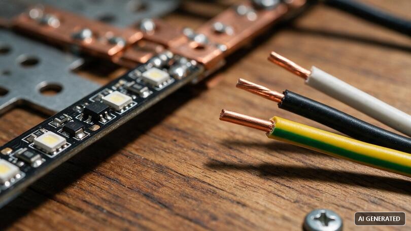
Here, the electrical wire color code table changes logic completely, and this is the most relevant chapter for those working with LED lighting. LED strips do not operate at 230V alternating current, but at extra-low voltage direct current, typically 12V or 24V. In direct current, there is no phase and neutral, but positive and negative poles, and the color code is different from that of alternating current.
Questions such as what the direct current electrical wire colors are, the positive negative electrical wire color, and whether the red wire is positive find their answer here. The most widespread convention in direct current is: red = positive (+), black = negative (–). However, attention: this convention does not have the same binding force as the AC code. In DC wiring, and particularly in LED strips, colors can vary by manufacturer, so the +/– marking and the silkscreen on the strip remain the definitive reference.
| DC Application | Positive (+) | Negative (–) | Notes |
|---|---|---|---|
| Monochrome LED strip 12V / 24V | Red | Black | Always verify the + / – silkscreen on the pad. |
| RGB LED strip | +12/24V common | R, G, B (color channels) | One common positive and three channels. |
| RGBW / RGBWW LED strip | + common | R, G, B, W (channels) | Like RGB with the addition of the white channel. |
| LED power supply (DC output) | V+ (often red) | V– (often black) | Terminals marked V+ / V–; respect polarity. |
How to recognize positive and negative by color
If you are wondering how to recognize the positive and negative wire by color and how to tell if a wire is positive or negative, you are asking crucial questions when powering an LED strip, because reversing polarity prevents it from turning on (and in some cases can damage components). The practical rule is: red is positive, black is negative, but this must always be cross-checked with the strip and controller silkscreen. In case of doubt, a multimeter in DC voltage mode resolves any uncertainty: by connecting the probes to the power supply output, a positive reading confirms the correspondence red probe = positive.
This is the point where knowledge of the electrical wire color code table translates directly into a successful LED assembly. An installer who knows both the AC code (upstream of the power supply) and the DC positive/negative logic (downstream) can create an LED strip lighting system that is safe from the panel to the last meter of profile.
The role of the power supply: from 230V AC to 12/24V DC
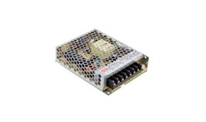
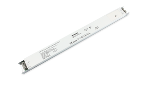
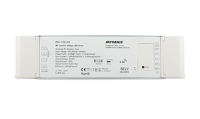
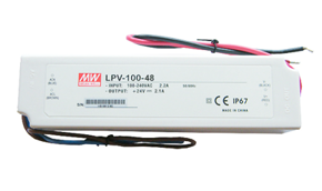
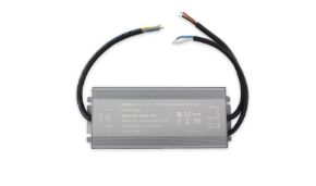
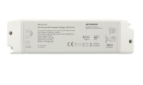
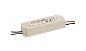
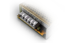
Between the 230V system and the LED strip, there is always a power supply (or driver), which converts the mains alternating current into the low-voltage direct current required by the LEDs. On the input side, the power supply respects the AC color code (brown phase, blue neutral, yellow-green ground where required); on the output side, it provides DC with V+ and V– terminals. Understanding this transition is essential: it is precisely at the power supply that the language of colors "changes language", moving from the phase/neutral logic to the positive/negative logic. You can find the complete range of LED strip power supplies in the Ledpoint catalog, with powers and voltages (12V and 24V) suitable for any project.
11. Volts, amps, watts, and current intensity: the electrotechnics you need
To correctly connect wires and size an LED system, knowing the colors is not enough: you need to understand the relationship between voltage (volts), current (amps), and power (watts). This section simply answers questions like "what are watts", "current intensity", "amp calculation", and "watt amp volt", because it is precisely this understanding that avoids undersized wires and voltage drops.
The fundamental formula
The basic relationship is Power (W) = Voltage (V) × Current (A). From this, we derive the current intensity: A = W ÷ V. Current is measured in amperes (the unit of measurement of current intensity), voltage in volts, power in watts. This is one of the most useful formulas in absolute terms, because it allows you to know how much current an LED strip draws and therefore what wire cross-section is needed.
Graphic 1 — Current drawn by an LED strip: 12V vs 24V at equal power
The graphic makes a design principle evident: at equal power, a 24V strip draws half the current of a 12V one. Less current means fewer losses in the conductors and less voltage drop. For this reason, on long runs, 24V is almost always the best choice. The question "what are watts" finds its operational answer here: watts are the absorbed power, and together with voltage, they determine the current that your wires will have to carry.
12. Color variations in international regulations
The electrical wire color code table we have described is the harmonized European one, but those working with imported equipment or on international projects must know that colors change from country to country. Questions about international electrical wire color regulations and Europe vs Italy electrical wire color standards arise precisely from this variety. The following table offers a synthetic comparison.
| Area / standard | Phase | Neutral | Ground |
|---|---|---|---|
| Harmonized Europe (IT included) | Brown / black / gray | Blue | Yellow-green |
| United Kingdom (post-harmonization) | Brown | Blue | Yellow-green |
| United Kingdom (old scheme) | Red | Black | Green / yellow-green |
| USA (typical 120/240V) | Black / red | White | Green or bare |
The most insidious case is the old British scheme, in which black was the neutral: the exact opposite of the DC logic where black is negative, and different from the European use of black as phase. This explains why the question "what does the white wire correspond to" can have different answers: in the USA, white is the neutral, while in the European code it does not have that meaning. The comparison demonstrates that the reference electrical wire color code table must always be related to the regulatory context of origin.
13. Materials and insulation of colored wires
Color is the visible part, but the insulation that carries it is what determines the safety, durability, and suitability of the wire for the installation environment. Those wondering what the difference is between various colored electrical wire materials must look beyond the tint: the same color code can cover very different insulations, each with specific temperature, flexibility, and fire behavior characteristics. The following table summarizes the most common materials.
| Insulation material | Main characteristics | Typical use |
|---|---|---|
| PVC | Economical, good dielectric rigidity, moderate temperatures. | Standard civil and industrial installations. |
| LSZH / LS0H (low smoke, zero halogen) | Low emission of toxic fumes in case of fire. | Crowded places, escape routes, public environments. |
| EPR / HEPR Rubber | High thermal resistance and good flexibility. | Heavy-duty applications and high temperatures. |
| Silicone | Resistance to very high temperatures, excellent flexibility. | Proximity to heat sources, lighting fixtures. |
For LED strips and their connections, the choice of insulation is far from secondary. In proximity to heating lighting fixtures, or in recessed installations such as plasterboard ceilings with LEDs, an insulation adequate to the temperature prevents premature aging and cracking. The question of how to choose wires resistant to high temperatures and wear finds its answer here: always match the insulation material to the actual installation conditions, not just the electrical capacity. Cable insulation resistance should also be periodically verified in systems subject to thermal stress.
14. Wire cross-section and voltage drop in LED strips
Color identifies the function, but it is the conductor cross-section (in mm²) that determines how much current it can safely carry and how much it contributes to voltage drop. This aspect is particularly critical in long LED strips, where an insufficient cross-section causes the typical fading brightness effect. Understanding "electrical system wire cross-section" completes the picture of workmanlike wiring.
Voltage drop: what it is and how to combat it
Voltage drop is the progressive decrease in voltage along a conductor or a very long LED strip. It is countered with three strategies: powering the strip from both ends, using conductors of adequate cross-section, and preferring 24V over 12V on long runs. The following graphic shows, in an indicative way, how the residual brightness at the end of the strip is maintained much better at 24V compared to 12V as length increases.
Graphic 2 — Residual brightness at the end of the run as length increases (indicative)
| Strip power | Current at 12V | Current at 24V | Observation |
|---|---|---|---|
| 24 W | 2.0 A | 1.0 A | Short runs, furniture, showcases. |
| 60 W | 5.0 A | 2.5 A | Kitchens, suspended ceilings. |
| 100 W | 8.3 A | 4.2 A | Medium environments; 24V recommended. |
| 200 W | 16.7 A | 8.3 A | Long installations; 24V strongly recommended. |
Respecting the correct cross-section of the connection cable is therefore as important as respecting the electrical wire color code table: color tells you what that wire is, cross-section tells you how much it can load. In domestic LED installations, an adequate cross-section and the use of 24V solve most fading brightness problems.
15. Wires for lighting and LED strips: colors and choices
In the world of lighting, wires have specific requirements. Those looking for lighting wires, colored light wires, colored wires for lamps, or colored lamp wires want reliable conductors, of the right cross-section, and with insulation suitable for the temperatures of lighting fixtures. In this section, we connect the electrical wire color code table to practical choices for an orderly and durable LED lighting installation.
Insulation color and color temperature: two concepts not to be confused
Be careful not to confuse the color of the insulation (which indicates the electrical function) with the color temperature of the light emitted by the LEDs, measured in kelvin. These are two different things: the first concerns wiring safety, the second the atmosphere of the environment. The following scale illustrates LED color temperature, a very hot topic along with the lumen watt table.
Graphic 3 — LED color temperature scale (kelvin)
The practical rule: warm white (2700–3000K) creates welcoming atmospheres in residential environments, neutral white (4000K) is ideal for kitchens and offices, cool white (5000–6500K) is used in technical and commercial environments. Our LED strips are available in all these temperatures, as well as RGB and tunable white versions.
The meaning of LED and dimmable
Two terms recur continuously in the sector. LED: is the acronym for Light Emitting Diode, the component that converts electrical energy into light with very high efficiency. Dimmable indicates an appliance whose light intensity can be regulated via a compatible dimmer. Not all strips and power supplies are dimmable: to regulate light, compatible components are needed, which we will see in the home automation section.
16. Other low-voltage colored wires: network, intercom, telephone, and corrugated tubes
Those looking for the electrical wire color code table often have doubts about other wiring that coexists in the same system: data network, intercom, telephone, and the corrugated tubes that house them. Although they are not power circuits, they also follow color codes, and it is useful to know them to avoid confusion. Here, we briefly cover network cable colors, intercom wire colors, telephone wire colors, and corrugated tube colors.
| Cable type | Typical colors | Function |
|---|---|---|
| Network cable (LAN, RJ45) | White/orange, orange, white/green, green pairs, etc. | Data transmission according to T568A/T568B scheme |
| Intercom cable | Various colors coded per terminal | Audio, call, door opener |
| Telephone cable | Colored pairs (e.g., white/blue) | Traditional telephone line |
| Corrugated tube | Gray, blue, yellow, red, etc. | Color to distinguish the type of system (power, data, etc.) |
An intelligent use of corrugated tube color helps to distinguish at a glance which conduits contain power, which contain data, and which contain other services, simplifying maintenance and expansions. Note: while in power circuits the color code is binding, in data wiring and conduit color, conventions and best practices prevail, which can vary between manufacturers and projects. The principle, however, remains the same as the electrical wire color code table: color serves to make the system immediately readable.
17. Home automation and LED strip control: dimmers, controllers, and smart relays
Intelligent lighting control is now an integral part of every modern project. After understanding colors, voltages, and connections, the next step is to govern the light: switching on, regulation, scenarios, and automations. This section connects the electrical wire color code table to the world of LED control, from dimmers to smart relays used in home automation.
Dimmers and controllers for LED strips
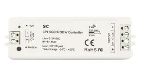
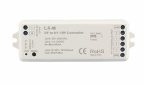
To regulate the intensity of a monochrome strip, a compatible dimmer is needed, while to manage the color and scenarios of RGB/RGBW strips, a controller is required. These devices are inserted into the DC circuit, between the power supply and the strip, respecting positive/negative polarity. The LED dimmers and controllers in the Ledpoint catalog cover the main needs, from simple dimmers to multi-zone systems.
Smart relays and automation (e.g., Shelly-type devices)
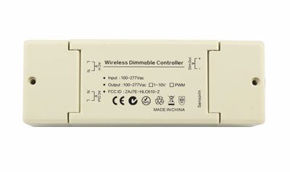
In modern home automation, small smart relays like those in the "Shelly" category allow controlling circuits from an app and integrating them into automatic scenarios, while maintaining traditional physical controls. These devices are connected respecting phase, neutral, and (where required) the control input: here too, the correct identification of wire colors is the premise of a safe connection. Paired with dimmers and controllers, they allow transforming a simple LED system into an intelligent, adjustable, and programmable lighting system.
18. How to identify electrical wires safely: step-by-step guide
Knowing how to read the electrical wire color code table is half the job; the other half is knowing how to apply it safely when colors are faded, inconsistent, or absent. Here is an essential procedure designed to answer questions on how to recognize electrical wires and how to distinguish electrical wires that every operator should follow.
- Cut off power: interrupt the power supply from the panel and block accidental restoration. This is the non-negotiable step;
- Verify absence of voltage: use a voltage tester or a multimeter to confirm that the conductors are no longer live before touching them.
- Observe the colors: compare the conductors with the color code table: yellow-green = ground, blue = neutral, brown/black/gray = phase.
- Do not blindly trust old systems: if the colors are not consistent, measure with a tool to establish the actual phase, neutral, and ground.
- Document corrections: if you correct a non-compliant system, it is important to note and, where possible, return the conductors to the standard color code.
The minimum tools for safe identification are a voltage tester and a multimeter capable of measuring AC and DC voltage. For LED installations, a small test power supply is also useful to verify strip polarity before final assembly. The question of which tools to use to identify electrical wires thus has a practical answer: the tool is what turns chromatic hypothesis into certainty.
19. Common mistakes to avoid with wire colors
Even knowing the electrical wire color code table, some mistakes recur with surprising frequency. Recognizing them in advance is the best way to avoid them and ensure a safe and compliant system.
Using yellow-green for anything other than ground
This is the most serious mistake in absolute terms. Yellow-green is reserved exclusively for ground: using it as phase or neutral is a regulatory violation that compromises the safety of the entire system and deceives anyone who intervenes later.
Confusing AC logic with DC logic
In alternating current, black is phase; in direct current, black is negative. Applying the wrong logic to the wrong context is a classic source of errors in LED strip wiring. Always keep the distinction clear between the 230V input of the power supply and the 12/24V output to the strip.
Trusting the color in an old system
In old systems, colors may not respect the current standard. Color is an indication, measurement is proof. Always verify with a tool to avoid interventions on misinterpreted conductors.
Reversing the polarity of the LED strip
Connecting positive to negative on an LED strip prevents it from turning on. Always check the +/– silkscreen and, in case of doubt, measure with a multimeter before applying power.
20. Applying the color code table to wiring Ledpoint LED strips
We arrive at the point where all theory becomes a project. A well-done LED strip installation starts precisely with the correct reading of the electrical wire color code table on both sides of the power supply. Here is how a typical connection chain is articulated.
Upstream (230V AC side): the power supply receives the phase (brown), the neutral (blue), and, where required, the ground (yellow-green). This is the domain of the alternating current color code. You can choose the suitable power supply from our LED power supplies, available in both 12V and 24V and in various powers, to correctly size the load.
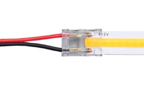
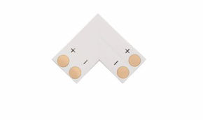
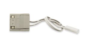
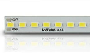
Downstream (DC side): from the V+/V– output of the power supply, the connection to the strip begins, where red is positive and black is negative. Our LED strips (monochrome, tunable white, RGB, and RGBW) feature polarity silkscreen on the pads for unambiguous connection. For clean and rapid joints, without soldering, quick connectors for LED strips are ideal, maintaining the correct channel correspondence even in RGB strips.
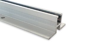
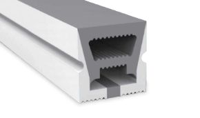
For installation and heat dissipation: inserting the strip into an aluminum profile improves heat dissipation and protects the conductors, prolonging the life of the installation. And if the project provides for light regulation or scenarios, LED dimmers and controllers complete the system, with the possibility of managing switching on even via home automation.
The message is simple: knowing the electrical wire color code table is not a theoretical exercise, but the competence that allows you to carry current from the panel to the last LED safely, neatly, and in compliance. At Ledpoint, you will find all the components of the chain (strips, power supplies, profiles, connectors, and controllers) designed to work together.
21. The market for wires and LED strips: some data
To frame the topic with some numbers: LED lighting has now almost completely replaced traditional sources in new installations, and the demand for LED strip solutions (from suspended ceilings to showcases, from kitchens to commercial spaces) grows year by year, driven by energy efficiency and installation flexibility. In this scenario, correct execution of connections is the factor that distinguishes a reliable system from one subject to early failures.
The following graphic reports an indicative estimate, based on technical assistance experience, of the most frequent causes of malfunction in amateur LED installations. As can be seen, many problems do not depend on the LEDs themselves, but on upstream errors related precisely to the topics of this guide.
Graphic 4 — Frequent causes of malfunction in LED installations (indicative estimate)
The striking fact is that more than half of the problems are attributable to incorrect colors/connections and poor electrical sizing, which is exactly what this guide helps to prevent. Investing ten minutes in correctly reading the electrical wire color code table and sizing the power supply and cross-section pays off in years of trouble-free operation.
22. Frequently asked questions about the electrical wire color code table
We collect here the most searched questions about colors, phase, neutral, ground, connections, and LED strips, with synthetic and immediately useful answers.
What are the electrical wire colors and how are they recognized?According to the current electrical wire color code table, blue is neutral, yellow-green is ground, and brown, black, and gray are the allowed colors for phase. In direct current, red is positive and black is negative. In old systems, the color must be verified with a tool. |
What color is the ground wire?The ground conductor is always and only yellow-green (bicolor), reserved exclusively for protection: no other conductor can be. |
What color is the neutral wire?The neutral is light blue (abbreviation N) and is the conductor that closes the circuit. It must be connected to the N terminal and still treated with caution. |
What are the wire colors for the phase?The phase is brown in single-phase; in three-phase, brown (L1), black (L2), and gray (L3) are used. In old systems, it could be red. |
Is the red wire positive?In direct current, yes: red is positive (+) and black is negative (–), as in LED strips. In alternating current, red often indicated a phase in old systems. |
How to recognize the positive and negative wire by color?In LED strips, red is positive and black is negative. Since the DC convention is not rigid, always verify the +/– silkscreen and, in case of doubt, measure with a multimeter in DC voltage mode. |
How are the blue and brown electrical wires connected?Blue (neutral) goes to the N terminal and brown (phase) to the L terminal of the appliance. This is the typical configuration of outlets, light points, and power supplies. |
What are the electrical wire colors for 220 volts?In the 230V single-phase system, brown is used for phase, blue for neutral, and yellow-green for ground, according to the harmonized European standard. |
What is the yellow-green wire for?It is the protective conductor (ground): in the event of a fault, it channels the leakage to the grounding system, allowing the residual current device to intervene. In practice, it protects people. |
How to tell if a wire is phase or neutral?Color gives an indication (brown/black/gray = phase, blue = neutral), but certainty is obtained with a voltage tester and multimeter, after cutting off power from the panel. |
What is the difference between a switch and a two-way switch?The switch turns on/off from a single point; the two-way switch commutes the phase and allows controlling the same light from two points. With an intermediate switch, you can reach three or more control points. |
What does the white wire correspond to?In the European code, white is not a main power color; in US standards, it indicates the neutral. In multi-core cables, it can be an auxiliary or signal conductor. |
What does "dimmable" mean?Dimmable indicates an appliance whose light intensity can be regulated with a compatible dimmer. For LED strips, a compatible power supply and dimmer/controller are required. |
Why choose 24V LED strips instead of 12V?For the same power, 24V strips draw half the current compared to 12V, reducing voltage drop and losses in long runs. You can find both voltages in the Ledpoint catalog. |
23. Electrical wire color code table: connect yes, but safely for everyone
The electrical wire color code table is much more than a scheme to memorize: it is a shared safety language that makes every system readable, repairable, and compliant. We have seen that blue is always the neutral and yellow-green is always the ground, that the phase lives among brown, black, and gray, and that in direct current (the territory of LED strips) the logic changes with red positive and black negative. We have traversed codes and types, typical connections, basic electrotechnics, regulations, materials, the relationship between volts, amps, and watts, and voltage drop, up to the concrete wiring of an LED system and its control in home automation.
The common thread, so to speak, is only one: color indicates the function, but measurement confirms reality. By combining knowledge of the color code table with instrumental verification, and choosing quality components from the panel to the last LED, you can create safe, durable, and elegant installations. The Ledpoint catalog with strips, power supplies, profiles, connectors, and controllers is designed precisely to accompany you in every phase of this journey.
This article was developed with the support of artificial intelligence and subsequently reviewed, corrected, and validated by the Ledpoint.it technical team, which guarantees its reliability and compliance with official sources.