








Amps and LED strips: the definitive technical guide for calculating current, cables, and power supplies.
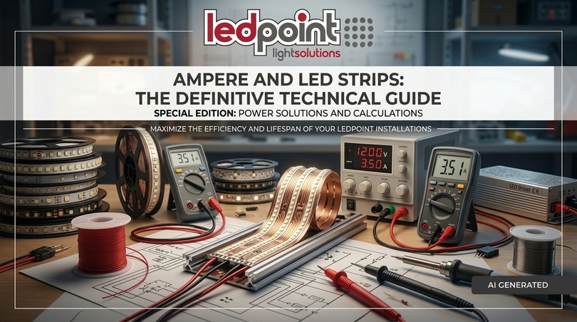
The ampere is the unit of measurement of electric current in the International System of Units, symbol A, and it indicates the amount of charge that flows through a cross-section of a conductor in one second. In an LED strip, amperes determine the heat produced, the voltage drop, the cable cross-section, the size of the power supply and the real lifespan of the installation.
Anyone designing linear lighting almost always thinks in watts: "I need 14.4 W/m for ten metres, so 144 watts." It is correct reasoning, but incomplete, because copper doesn't know about watts: copper knows about amperes. It is amperes, and only amperes, that heat a PCB track thirty-five microns thick; it is amperes that make the voltage collapse at the far end of a five-metre reel; it is amperes that decide whether a 0.5 mm² cable is enough or whether you need to move up to 1.5 mm². Every premature failure of an LED strip, every final section dimmer than the first, every power supply that goes into protection after twenty minutes of operation has at its root an amperage calculation that was not done, or was done badly.
This guide draws on the technical experience of Ledpoint, a company based in Faenza specialising in the manufacture and customisation of professional LED strips, and it aims to be three things at once: a rigorous theoretical manual on what amperes are and where they sit in the International System, an operational manual with formulas, conversion tables and ready-to-use values, and a configurator that lets you work out in a few seconds how many amps a given installation really draws.
In this article...
1. Ampere: definition, symbol and unit of measurement
Before sizing any system you need to be clear about what you are measuring. The ampere is not a commercial label printed on the back of a power supply: it is one of the seven base units of the International System, the only one entirely dedicated to electrical phenomena, and its definition changed in 2019 with a reform that redesigned metrology worldwide. Understanding this step is not an academic exercise: it explains why modern instruments are so precise and why a value stated in amperes means the same thing in Faenza, Shenzhen or Boston.
What is an ampere: the essential definition
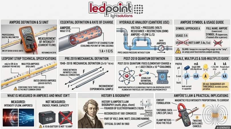
The ampere is the unit of measurement of electric current, that is, the amount of electric charge flowing through the cross-section of a conductor per unit of time. One ampere corresponds to one coulomb of charge per second: 1 A = 1 C/s. Since one coulomb equals approximately 6.241 × 10¹⁸ elementary charges, saying that one ampere is flowing in a cable means that every second more than six billion billion electrons pass through that cross-section.
The most useful definition of the ampere on site, however, is a different one, and it is hydraulic in nature. If we imagine an electrical circuit as a plumbing system, voltage in volts corresponds to pressure, resistance in ohms corresponds to a narrowing of the pipe, and amperes correspond to the flow rate of water, that is, the litres per second actually flowing. A pipe can be under pressure without a single litre of water passing through it, just as a socket has 230 volts even when no appliance is connected and the current is zero. It is amperes, not volts, that tell us how hard the system is actually working.
Ampere symbol: how to write it correctly
The symbol for the ampere is a capital letter A, with no full stop and no plural: you write 5 A, not 5 amp, 5 As or 5 a. The rule applies to all units derived from a surname, which take a capital initial in the symbol and a lower-case initial in the full name: so you say "five amperes" and write "5 A". The short form "amp", very common in English-speaking countries, and misspellings such as "amper" frequently typed into search engines, are acceptable jargon in speech but incorrect in technical documentation, a specification or a product data sheet.
In LED strip data sheets the amperage figure appears in three different places, and it is worth knowing how to tell them apart. The first is the current drawn per metre, typically expressed in amps per metre or obtainable by dividing watts per metre by the voltage. The second is the maximum permissible amps on the PCB, the limit beyond which the copper tracks start to overheat. The third is the rated output amps of the power supply, that is, how many amps the device can deliver continuously. Confusing these three amperage values is the most common mistake among those approaching low-voltage linear lighting for the first time.
The technical definition of the ampere in the International System
Until 20 May 2019 the ampere was defined mechanically: it was the constant current which, if maintained in two straight parallel conductors of infinite length and negligible cross-section, placed one metre apart in a vacuum, would produce between them a force equal to 2 × 10⁻⁷ newtons per metre. It was an elegant definition but experimentally awkward, because no laboratory in the world has conductors of infinite length.
Since 2019 the ampere has been defined by fixing the numerical value of the elementary charge e at 1.602176634 × 10⁻¹⁹ coulombs, where the coulomb equals the ampere-second. In other words, the ampere no longer depends on a mechanical force experiment but on a fundamental constant of nature, reproducible in any laboratory with single-electron devices or by combining the Josephson effect and the quantum Hall effect. This revision, adopted by the General Conference on Weights and Measures, made the ampere a unit that is stable by definition and not subject to drift over time. Those who wish to learn more about the reform can consult the official documentation of the Bureau International des Poids et Mesures or the encyclopaedia entry on the ampere.
The ampere scale: multiples, submultiples and orders of magnitude
In the world of LED strips you work with currents ranging from the milliamps of a single SMD chip to the tens of amps of an extensive retail installation. Knowing the ampere scale lets you read a data sheet correctly and avoid being off by three orders of magnitude, a mistake that is far from rare when comparing values expressed in different units.
| Prefix | Symbol | Value in amperes | Typical example in the LED industry |
|---|---|---|---|
| Microampere | µA | 0.000001 A | Leakage current of a capacitor |
| Milliampere | mA | 0.001 A | Current drawn by a single SMD 2835 LED (about 60 mA) |
| Ampere | A | 1 A | 24V strip at 14.4 W/m over just under 1.7 metres |
| Kiloampere | kA | 1,000 A | Prospective short-circuit current of a switchboard |
The most frequently used submultiple is undoubtedly the milliampere. One milliampere is one thousandth of an ampere, so 1,000 mA make exactly 1 A and 500 mA make half an ampere. The value of 30 mA, i.e. thirty thousandths of an ampere, is the tripping threshold of the high-sensitivity residual current device required for domestic installations: it is a current so small as to be invisible to any power measurement, yet it is enough to cause ventricular fibrillation in the human body, which is why electrical safety is decided in milliamps and not in kilowatts.
What is measured in amperes and what is not
What is measured in amperes is current intensity, that is, a flow. Neither energy, nor power, nor battery capacity is measured in amperes. A very common mistake is to say that a battery "has 10 amps": that quantity is the ampere-hour (Ah), which measures charge capacity and not an instantaneous current in amperes. A 10 Ah battery can deliver ten amps for one hour, or one amp for ten hours, or twenty amps for half an hour, with the necessary corrections for efficiency and Peukert's law. We will return to this distinction at length in the chapter on battery power.
2. History of the ampere and Ampère's law
Behind every unit of measurement there is a biography, and that of the ampere is particularly instructive because it tells of the exact moment when electricity and magnetism stopped being two separate phenomena. Knowing the origin of the term ampere is not just a matter of historical curiosity: it helps you understand why a current-carrying cable generates a magnetic field, why clamp meters work without breaking the circuit, and why installations carrying many amps require attention to electromagnetic interference.
Who was Ampère?
André-Marie Ampère, born in Lyon in 1775 and died in Marseille in 1836, was a French mathematician, physicist and chemist, largely self-taught. In September 1820, just one week after witnessing a demonstration of Oersted's experiment showing a magnetic needle deflected by a current-carrying wire, Ampère formulated the theory linking electric current and magnetism, effectively founding the discipline he himself called electrodynamics. It was Ampère who showed that two parallel current-carrying conductors attract each other if the currents flow in the same direction and repel each other if they flow in opposite directions: that very experiment, over a century later, would become the basis of the official definition of the ampere adopted in 1948 and in force until 2019.
International recognition came posthumously. In 1881, at the International Congress of Electricians in Paris, it was decided to give the name ampere to the practical unit of electric current, in tribute to the work of the French physicist. It was a choice consistent with the whole electrical nomenclature of the time, which was naming its quantities after the surnames of the pioneers: volt after Alessandro Volta, ohm after Georg Simon Ohm, watt after James Watt, coulomb after Charles-Augustin de Coulomb. The ampere then officially entered the International System as a base unit in 1960, together with the metre, kilogram, second, kelvin, mole and candela.
What Ampère's law says
Ampère's law, in its circuital form, states that the line integral of the magnetic field around a closed loop is proportional to the current enclosed by that loop. In practical terms: the more amps flow in a conductor, the stronger the magnetic field surrounding it, and the strength of that field decreases as the distance from the conductor increases. Maxwell later completed the law by adding the displacement current term, making it one of the four fundamental equations of electromagnetism.
For those installing LED strips, this law has three very concrete consequences. The first is that every cable carrying many amps radiates a magnetic field that can disturb nearby data lines, in particular the digital signals of SPI controllers and DALI buses. The second is that by twisting positive and negative together, or keeping them adjacent, the fields generated by the two conductors largely cancel each other out, drastically reducing emissions: this is why separating the two poles along different routes is discouraged. The third is that clamp meters measure amps precisely by reading that magnetic field, without the need to break the circuit.
From the 1948 ampere to the 2019 ampere
The transition between the two definitions deserves a comparison table, because it clearly illustrates how modern metrology chose to anchor units to fundamental constants rather than to material standards or idealised experiments.
| Criterion | 1948–2019 definition | Definition since 2019 |
|---|---|---|
| Reference | Force between two parallel conductors | Fixed elementary charge e |
| Fixed value | µ0 = 4π × 10-7 H/m | e = 1.602176634 × 10⁻¹⁹ C |
| Reproducibility | Current balance, high uncertainty | Single-electron pumps, minimal uncertainty |
| Nature | Mechanical and electromagnetic | Quantum |
| Dependence on other units | On metre, kilogram and second | On the second only |
The practical result is that today a multimeter calibrated against a primary standard measures amps with an uncertainty that, in national metrology laboratories, falls below one part per million. For lighting engineering this precision is more than sufficient, but it guarantees that the current values declared by a serious manufacturer such as Ledpoint are comparable with those of any other laboratory in the world.
3. Amps, volts, watts and ohms: formulas and differences
We now come to the operational heart of the matter. Almost all the questions our technical service receives concern the relationships between amps, volts and watts: how many watts is one amp, how many amps is one kilowatt, what is the difference between volts and amps. These are legitimate questions with precise answers, provided you accept one principle: none of these quantities converts directly into another, because they are physically different quantities. They can only be related to each other when a third value is known.
Ohm's law and the four fundamental quantities
The basic electrical triangle links four quantities: voltage V measured in volts, current I measured in amperes, resistance R measured in ohms and power P measured in watts. Ohm's law states that voltage equals current multiplied by resistance, while Joule's law links power to the product of voltage and current.
| Quantity | Symbol | Unit | Main formula | Derived formulas |
|---|---|---|---|---|
| Voltage | V | volt | V = R × I | V = P / I V = √(P × R) |
| Current | I | ampere | I = V / R | I = P / V I = √(P / R) |
| Resistance | R | ohm | R = V / I | R = V² / P R = P / I² |
| Power | P | watt | P = V × I | P = R × I² P = V² / R |
The amperage formula you need in ninety-five per cent of real cases is just one: I = P / V, that is, amps equal watts divided by volts. It is the formula that takes you from the commercial figure printed on the packaging of a strip, expressed in watts per metre, to the engineering figure needed to size cables and protection devices, expressed in amps. Memorise it: the whole of this manual revolves around this division.
What is the difference between volts and amps
It is the most searched question of all and also the most misunderstood. Volts measure the potential difference, i.e. the push that sets charges in motion; amps measure how many charges actually move. A 9 V battery has a higher voltage than a 12 V car battery per single cell, yet the car battery can deliver hundreds of amps and the 9 V battery cannot. Voltage tells you how hard the system "pushes"; amps tell you how much the system "passes".
In LED installations this difference translates into an important operating rule. The voltage is imposed by the power supply and must match that of the strip; the amps, on the other hand, are demanded by the load and determined by the installed length. If we connect a 24V strip to a 12V power supply we get dim light or none at all; if we connect a 5 A strip to a power supply capable of delivering 20 A, the strip will still draw only its 5 amps, without any damage. Voltage must be matched to the volt; available amps can be generous. It is an asymmetry that surprises many DIY installers and is well worth fixing firmly in mind.
What is the difference between watts and amps
The watt measures power, that is, energy transferred per unit of time; the ampere measures current. The link is P = V × I, so the same number of watts corresponds to a completely different number of amps depending on the operating voltage. One hundred and twenty watts at 12 volts means ten amps; the same one hundred and twenty watts at 24 volts means five amps; at 230 volts they become just 0.52 amps. This is exactly why the whole professional linear lighting industry has progressively abandoned 12 volts in favour of 24 volts and, for long runs, 48 volts.
Volt-amperes, watts and power factor
Power supply data sheets sometimes show the volt-ampere (VA) alongside the watt. The volt-ampere measures apparent power, i.e. the simple product of RMS volts and RMS amps, while the watt measures active power, i.e. the power actually converted into useful work. The ratio between the two is the power factor, indicated as PF or cosφ. A 150 W power supply with a power factor of 0.95 draws about 158 VA from the mains, which at 230 volts corresponds to about 0.69 amps of line current. Switchboards are sized on apparent power, not active power, because the amps flowing through the cables are the apparent ones. Power supplies with active power factor correction, found in the professional range of Ledpoint power supplies, significantly reduce this gap and limit the amps drawn upstream.
Amperes, coulombs, joules and farads: the lesser-known relatives
For completeness, it is worth clarifying the relationships between the ampere and the other derived units that appear in electronic component data sheets. One ampere for one second produces one coulomb of charge; one ampere flowing across a potential difference of one volt for one second transfers one joule of energy; one farad is the capacitance of a capacitor which, charged with one coulomb, shows one volt across its terminals. From this follows a formula widely used in sizing power supply filter capacitors: the voltage change of a capacitor equals the amps multiplied by time and divided by the capacitance in farads. For the installer it is a detail; for the electronics designer it is daily bread.
4. Amps, watts and volts conversion tables
This section is designed to be consulted directly on site. We have collected the most requested conversions between amps, watts, volts and kilowatts at the voltages actually used in LED lighting and domestic installations. All values derive from direct application of the relationship P = V × I and, for single-phase mains, assume a unity power factor unless otherwise stated.
From watts to amps at LED strip operating voltages
The following table answers in one go questions such as "how many amps does a 100 W strip draw" or "how many watts is 1 amp". It reads in both directions: once the voltage is chosen, divide watts to get amps and multiply amps to get watts.
| Power | Amps at 5V | Amps at 12V | Amps at 24V | Amps at 48V | Amps at 230V |
|---|---|---|---|---|---|
| 10 W | 2.00 A | 0.83 A | 0.42 A | 0.21 A | 0.04 A |
| 25 W | 5.00 A | 2.08 A | 1.04 A | 0.52 A | 0.11 A |
| 50 W | 10.00 A | 4.17 A | 2.08 A | 1.04 A | 0.22 A |
| 75 W | 15.00 A | 6.25 A | 3.13 A | 1.56 A | 0.33 A |
| 100 W | 20.00 A | 8.33 A | 4.17 A | 2.08 A | 0.43 A |
| 150 W | 30.00 A | 12.50 A | 6.25 A | 3.13 A | 0.65 A |
| 200 W | 40.00 A | 16.67 A | 8.33 A | 4.17 A | 0.87 A |
| 300 W | 60.00 A | 25.00 A | 12.50 A | 6.25 A | 1.30 A |
| 500 W | 100.00 A | 41.67 A | 20.83 A | 10.42 A | 2.17 A |
| 1,000 W (1 kW) | 200.00 A | 83.33 A | 41.67 A | 20.83 A | 4.35 A |
The table clearly shows the advantage of 24 volts: for the same installed power, the amps required are exactly half those at 12 volts. Halving the amps means halving the voltage drop along the strip and reducing Joule losses in the cables by a factor of four, since these depend on the square of the current. This is why the entire professional range of Ledpoint 24V LED strips is today the reference standard for architectural and retail installations, while 12V LED strips remain preferable only where a twelve-volt infrastructure already exists, typically in the marine, motorhome and automotive sectors.
From amps to watts: the reverse reading
Many power supplies are rated in amps rather than watts, especially in the metal-case format. Knowing how many watts correspond to a given number of amps lets you check compatibility with the chosen strip at a glance.
| Current | Watts at 12V | Watts at 24V | Watts at 48V | Metres of 14.4 W/m strip at 24V |
|---|---|---|---|---|
| 1 A | 12 W | 24 W | 48 W | 1.67 m |
| 2 A | 24 W | 48 W | 96 W | 3.33 m |
| 3 A | 36 W | 72 W | 144 W | 5.00 m |
| 5 A | 60 W | 120 W | 240 W | 8.33 m |
| 6.25 A | 75 W | 150 W | 300 W | 10.42 m |
| 8.33 A | 100 W | 200 W | 400 W | 13.89 m |
| 10 A | 120 W | 240 W | 480 W | 16.67 m |
| 12.5 A | 150 W | 300 W | 600 W | 20.83 m |
| 15 A | 180 W | 360 W | 720 W | 25.00 m |
| 20 A | 240 W | 480 W | 960 W | 33.33 m |
Kilowatts and amps: questions about the home electrical system
"How many amps is one kilowatt?" is one of the most frequent searches of all, and the answer depends entirely on the voltage and the type of mains supply. On a 230-volt single-phase supply one kilowatt corresponds to about 4.35 amps with unity power factor; on a 400-volt three-phase supply the same kilowatt corresponds to about 1.44 amps per phase. In the other direction, one amp at 230 volts is worth 230 watts, i.e. 0.23 kW.
| Contracted power | Amps at 230V single-phase | Amps at 400V three-phase | Practical notes |
|---|---|---|---|
| 1 kW | 4.35 A | 1.44 A | About 240 metres of 24V strip at 4.8 W/m |
| 3 kW | 13.04 A | 4.33 A | Standard domestic contract, 16 A limit |
| 4.5 kW | 19.57 A | 6.50 A | Upgraded domestic contract |
| 6 kW | 26.09 A | 8.66 A | Homes with heat pump or induction hob |
| 10 kW | 43.48 A | 14.43 A | Small commercial businesses |
| 15 kW | 65.22 A | 21.65 A | Medium retail, extensive lighting |
It is worth noting how reassuring these numbers are for LED lighting designers: a retail installation of two hundred linear metres of 14.4 W/m strip draws 2,880 watts, i.e. less than thirteen amps on the 230-volt line, while requiring one hundred and twenty amps in total on the low-voltage side. It is yet another demonstration of how crucial it is always to specify which voltage an amperage value refers to.
How many amps does household electricity have
The most common Italian domestic meter is set at 3 kW with a tolerance allowing draws of up to 3.3 kW before tripping, which is equivalent to about 14.3 amps. The main circuit breaker installed downstream is typically rated 16 A or 20 A, while individual lighting circuits are protected at 10 A and socket circuits at 16 A. A 10-amp lighting circuit at 230 volts can theoretically supply 2,300 watts of equipment, but good practice requires not exceeding eighty per cent of the rating in continuous service, i.e. about 1,840 watts. Considering that an efficient LED power supply draws about ten per cent more than the power it delivers, a single domestic lighting circuit can comfortably supply over one hundred metres of 14.4 W/m strip.
5. Why amps are decisive in LED strips
We have built the theoretical foundations; now let's move on to the applied heart of this guide. An LED strip is a deceptively simple object: a flexible printed circuit eight or ten millimetres wide, often less than two thick, on which hundreds or thousands of LED chips are soldered, powered by low-voltage direct current. It is precisely this extreme geometry, long and very thin, that makes amps a critical variable in a way that has no equivalent in any other luminaire.
The LED strip as a distributed load, not a concentrated one
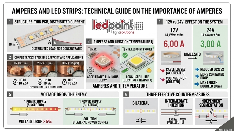
A spotlight draws its amps at one precise point. An LED strip, by contrast, is a distributed load: each cuttable segment draws its own share of current along the entire run. It follows that the amps do not remain constant along the strip, but decrease progressively. At the feed point, all the amps required by the entire length flow; at mid-strip about half of them flow; at the far end the remaining amps are only those of the last segment. This decreasing profile is the mathematical reason why the voltage drop along a strip is not linear but parabolic, and why traditional cable voltage-drop tables cannot be applied directly to strips.
The copper tracks of the PCB and their current capacity
The conductive tracks of an LED strip are made of laminated copper, with standard thicknesses of 1 ounce (35 microns), 2 ounces (70 microns) or, in high-performance series, 3 ounces (105 microns). The usable width of the tracks in a 10 mm strip is between 1.5 and 3 millimetres per pole. A copper cross-section 2 mm wide and 35 microns thick corresponds to just 0.07 mm²: a ridiculous cross-section compared with that of an ordinary 1.5 mm² cable.
| Copper thickness | Cross-section with 2 mm track | Recommended continuous amps | Typical Ledpoint application |
|---|---|---|---|
| 1 oz (35 µm) | 0.070 mm² | up to 2.5 A | Standard 4.8–9.6 W/m strips |
| 2 oz (70 µm) | 0.140 mm² | up to 5 A | 14.4–19.2 W/m strips and COB |
| 3 oz (105 µm) | 0.210 mm² | up to 7.5 A | High-power and high-density strips |
For this reason all the LED strips selected by power in the catalogue declare the maximum length that can be fed from one end: it is not a commercial limit, it is a physical limit imposed by the amps the copper can carry without heating beyond permitted values.
Amps, junction temperature and lumen depreciation
The amps flowing through each LED directly determine the power dissipated and therefore the junction temperature, indicated as Tj. For every ten degrees of junction temperature increase, lumen depreciation accelerates significantly and the L70 useful life, i.e. the time needed for the luminous flux to fall to seventy per cent of its initial value, can be reduced by as much as thirty or forty per cent. A strip run at the limit of its rated amps, installed without a heat-sinking profile and enclosed in a plasterboard cove with no air circulation, can lose in three years the brightness it should have lost in ten.
The most effective countermeasure is surprisingly simple and is called derating: you choose a more powerful strip than necessary and run it dimmed, reducing the amps actually in play. A 19.2 W/m strip dimmed to seventy per cent produces the same flux as a 14.4 W/m strip at one hundred per cent, but with much lower junction temperatures and a much longer useful life. Installing it in Ledpoint aluminium profiles completes the job, because extruded aluminium acts as a linear heat sink and lowers the operating temperature by as much as fifteen or twenty degrees compared with direct application on plasterboard.
Why moving from 12V to 24V halves the amps
Let's go back to the formula I = P / V. For the same installed power, doubling the voltage halves the amps. The consequences cascade through the whole installation and deserve to be spelled out one by one, because they form the strongest technical argument in favour of twenty-four volts.
| Parameter | 12V strip 14.4 W/m × 5 m | 24V strip 14.4 W/m × 5 m | Benefit |
|---|---|---|---|
| Total power | 72 W | 72 W | Unchanged |
| Amps drawn by the load | 6.00 A | 3.00 A | Halved |
| Cable losses (R = 0.1 Ω) | 3.60 W | 0.90 W | Reduced by a factor of 4 |
| Drop at end of strip | about 1.3 V (10.8%) | about 0.7 V (2.9%) | Much smaller |
| Max length from one end | typically 5 m | typically 10 m | Doubled |
| Recommended cable section | 1.5 mm² | 0.75 mm² | Smaller and cheaper |
In short: moving from twelve to twenty-four volts doesn't change the light, but it radically changes the electrical system behind it. For continuous installations longer than fifteen linear metres it is even worth considering forty-eight volts, available in the range of professional power supplies, where the amps drop to a quarter of those at twelve volts.
6. Voltage drop: enemy number one
If we had to name a single phenomenon responsible for most disappointing LED installations, it would be voltage drop. It shows itself with an unmistakable symptom: the strip is bright near the power supply and progressively dimmer the further you move away, often with a colour shift towards yellow in white tones and towards red in RGB. The cause is always the same: the amps flowing through the resistance of the copper tracks produce a voltage loss that accumulates metre after metre.
The physics of the phenomenon
Ohm's law applied to the conductor tells us that the voltage drop equals the amps flowing through it multiplied by its resistance: ΔV = R × I. In an LED strip, the resistance per metre of track is in the order of 0.15–0.45 ohms depending on copper thickness, and the amps decrease progressively along the run. Integrating the contribution of each segment, the total drop at the end of the strip turns out to be half of what it would be if all the amps travelled the entire length, according to the relationship ΔV = (Rtot × Itot) / 2 per conductor, to be doubled taking into account the outgoing and return paths.
The most insidious consequence is that the phenomenon grows with the square of the length: doubling the metres does not double the drop but quadruples it, because both the amps and the resistance travelled double at the same time. This is why a five-metre strip works superbly while the same strip at ten metres, fed from one end only, is unacceptable.
Voltage drop table as a function of amps
The following table shows values measured on the Ledpoint test bench for a 2-ounce copper strip with a density of 120 LEDs/m, fed from one end. The data are indicative and vary with ambient temperature, but they provide a reliable order of magnitude.
| Length | Input amps (24V, 14.4 W/m) | Estimated drop | Voltage at end of strip | Flux loss | Assessment |
|---|---|---|---|---|---|
| 2 m | 1.20 A | 0.15 V | 23.85 V | less than 1% | Excellent |
| 5 m | 3.00 A | 0.70 V | 23.30 V | about 3% | Excellent |
| 8 m | 4.80 A | 1.60 V | 22.40 V | about 7% | Acceptable |
| 10 m | 6.00 A | 2.50 V | 21.50 V | about 11% | Borderline |
| 15 m | 9.00 A | 5.60 V | 18.40 V | over 25% | Avoid |
| 20 m | 12.00 A | 9.90 V | 14.10 V | over 45% | Unacceptable |
The operating threshold Ledpoint recommends is a maximum drop of five per cent of the nominal voltage: 0.6 V on a 12-volt system, 1.2 V on a 24-volt system, 2.4 V on a 48-volt system. Beyond this threshold the luminance difference between the start and end of the strip becomes perceptible to the human eye in an overall view, particularly on continuous surfaces such as perimeter coves and light slots.
The three countermeasures that really work
Double-end feeding
Connecting the power supply to both ends of the strip is the cheapest and most effective countermeasure. Feeding from both ends halves the amps entering from each end, and the maximum drop, which moves to the centre of the strip, is reduced to a quarter compared with single-end feeding. A ten-metre strip fed from both ends behaves exactly like two five-metre strips side by side.
Intermediate power injection
In long installations a power cable is run parallel to the strip and connected at several points, typically every five metres. Having a much larger cross-section than the PCB tracks, the parallel cable carries the amps with negligible losses and reinjects them where they are needed. It is the standard technique for perimeter light slots in commercial spaces and requires quality LED strip connectors or, preferably, soldered joints.
Segmentation into independent runs
Dividing the installation into runs of five or six metres, each with its own power supply or its own output, eliminates the problem at the root. The extra cost is modest compared with the risk of having to redo the installation. When several power supplies are used on the same lighting line, it is essential to connect the negatives together while keeping the positives separate, to avoid potential differences between adjacent segments and to ensure a common reference for control signals.
7. How to calculate the amps of an LED strip
This is the most operational section of the entire guide. The procedure below is the one Ledpoint's technical service applies every day to validate customers' projects, and it is organised in six consecutive steps. Following it in the order given reduces the chance of undersizing an installation to practically zero.
Step one: read the power per metre on the data sheet
The starting point is always the specific power, expressed in watts per metre. Ledpoint data sheets show this value next to the total power of the reel: a label such as "14.4 W/m (72 W)" means the strip draws 14.4 watts for every metre and 72 watts over the entire five-metre reel. Be careful not to confuse real power with the nominal power declared by some manufacturers based simply on the chip count: Ledpoint always declares the value measured at thermal steady state, not the theoretical one.
Step two: determine the effective length
You must measure the length actually installed, not the length of the reel. Strips can be cut at fixed intervals, typically every 2.5, 3.33, 5 or 10 centimetres depending on density and voltage, so the effective length must be rounded up to the next usable cut. If the project calls for 3.40 metres on a strip cuttable every 5 cm, the length to use in the amperage calculation is 3.45 metres.
Step three: calculate the total power
Total power in watts = power per metre × length in metres. With 14.4 W/m over 3.45 metres we get 49.68 watts. It is a trivial operation, but it must be done for each individual run, not for the installation as a whole, because each run will have its own amps and its own power supply.
Step four: apply the amperage formula
Amps = total watts divided by system volts. In our example: 49.68 W / 24 V = 2.07 amps. This is the current that will flow in the supply cable and in the initial tracks of the strip. If the system were 12 volts, the same 49.68 watts would require 4.14 amps, exactly double.
Step five: add the safety margin
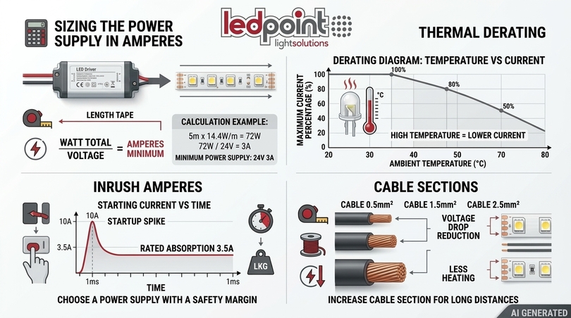
The calculated value is the nominal steady-state value under ideal conditions. Reality requires a margin for three concrete reasons: manufacturing tolerance on declared power, typically five per cent; inrush current at switch-on, which can temporarily exceed the nominal value; component ageing and possible future extension of the installation. Ledpoint recommends a minimum margin of twenty per cent for fixed installations in air-conditioned environments and thirty per cent for installations in hot environments, in closed profiles, or operating more than twelve hours a day.
In the example: 2.07 A × 1.3 = 2.69 amps. The power supply must therefore have a rated output current equal to or greater than 2.69 A at 24 volts, i.e. at least 65 watts. The next commercial size up is typically 75 W / 3.125 A, perfectly adequate.
Step six: check the maximum feedable length
The last check, often forgotten. Even if the power supply is more than adequate, the strip may not tolerate the required amps on its own tracks. You must check that the length of the run does not exceed the maximum value declared for feeding from one end. A reliable rule of thumb: the product of input amps and metres of run should not exceed 30 for 2-ounce copper strips and 15 for 1-ounce strips. In our example 2.07 × 3.45 = 7.14, well within the limits.
Complete calculation examples
| Application | Strip | Metres | Total watts | Nominal amps | Amps with 30% margin | Recommended power supply |
|---|---|---|---|---|---|---|
| Under-cabinet kitchen | 24V 9.6 W/m | 3.0 | 28.8 W | 1.20 A | 1.56 A | 24V 40W (1.67 A) |
| Living room cove | 24V 14.4 W/m | 9.0 | 129.6 W | 5.40 A | 7.02 A | 24V 200W (8.33 A) |
| Bathroom mirror | 24V 4.8 W/m | 2.4 | 11.5 W | 0.48 A | 0.62 A | 24V 20W (0.83 A) |
| Retail shop window | 24V 19.2 W/m | 12.0 | 230.4 W | 9.60 A | 12.48 A | 24V 320W (13.3 A) |
| Indoor staircase | 24V 6.0 W/m COB | 15.0 | 90.0 W | 3.75 A | 4.88 A | 24V 150W (6.25 A) |
| Hotel corridor | 48V 14.4 W/m | 25.0 | 360.0 W | 7.50 A | 9.75 A | 48V 480W (10 A) |
| Custom furniture | 12V 4.8 W/m | 1.5 | 7.2 W | 0.60 A | 0.78 A | 12V 12W (1 A) |
| Office light slot | 24V 24 W/m | 20.0 | 480.0 W | 20.00 A | 26.00 A | 2 × 24V 350W double-end |
Look at the last row: twenty metres of high-power strip require twenty-six amps with margin, a value that no single compact power supply handles easily and that would in any case require cables of substantial cross-section. The correct solution is to segment into two ten-metre runs with independent feeds, or to move to a higher voltage. When the design amps exceed fifteen, the right question is not "which power supply should I buy" but "how do I redesign the topology".
8. Ledpoint amperage configurator
We have translated the entire calculation procedure into a tool you can use directly on this page, built entirely in HTML and CSS without any external scripts: select the system voltage and the power per metre of your strip and you immediately get the amps drawn, the amps with safety margin, the recommended cable cross-section and the appropriate power supply size for eight typical lengths. All values are calculated with the formula amps equal watts divided by volts and with a thirty per cent safety margin, in line with Ledpoint's technical recommendations.
| Length | Power | Amps | Amps +30% | Cable section | Power supply | Feed |
|---|---|---|---|---|---|---|
| 1 m | 4.8 W | 0.40 A | 0.52 A | 0.50 mm² | 20 W | one end |
| 2 m | 9.6 W | 0.80 A | 1.04 A | 0.50 mm² | 20 W | one end |
| 3 m | 14.4 W | 1.20 A | 1.56 A | 0.50 mm² | 20 W | one end |
| 5 m | 24.0 W | 2.00 A | 2.60 A | 0.75 mm² | 40 W | one end |
| 8 m | 38.4 W | 3.20 A | 4.16 A | 1.00 mm² | 60 W | both ends recommended |
| 10 m | 48.0 W | 4.00 A | 5.20 A | 1.00 mm² | 75 W | both ends |
| 15 m | 72.0 W | 6.00 A | 7.80 A | 1.50 mm² | 100 W | both ends |
| 20 m | 96.0 W | 8.00 A | 10.40 A | 1.50 mm² | 150 W | both ends |
| Length | Power | Amps | Amps +30% | Cable section | Power supply | Feed |
|---|---|---|---|---|---|---|
| 1 m | 9.6 W | 0.80 A | 1.04 A | 0.50 mm² | 20 W | one end |
| 2 m | 19.2 W | 1.60 A | 2.08 A | 0.75 mm² | 30 W | one end |
| 3 m | 28.8 W | 2.40 A | 3.12 A | 0.75 mm² | 40 W | one end |
| 5 m | 48.0 W | 4.00 A | 5.20 A | 1.00 mm² | 75 W | one end |
| 8 m | 76.8 W | 6.40 A | 8.32 A | 1.50 mm² | 100 W | both ends |
| 10 m | 96.0 W | 8.00 A | 10.40 A | 1.50 mm² | 150 W | both ends |
| 15 m | 144.0 W | 12.00 A | 15.60 A | 2.50 mm² | 200 W | both ends |
| 20 m | 192.0 W | 16.00 A | 20.80 A | 4.00 mm² | 250 W | both ends |
| Length | Power | Amps | Amps +30% | Cable section | Power supply | Feed |
|---|---|---|---|---|---|---|
| 1 m | 14.4 W | 1.20 A | 1.56 A | 0.50 mm² | 20 W | one end |
| 2 m | 28.8 W | 2.40 A | 3.12 A | 0.75 mm² | 40 W | one end |
| 3 m | 43.2 W | 3.60 A | 4.68 A | 1.00 mm² | 60 W | one end |
| 5 m | 72.0 W | 6.00 A | 7.80 A | 1.50 mm² | 100 W | both ends recommended |
| 8 m | 115.2 W | 9.60 A | 12.48 A | 2.50 mm² | 150 W | both ends |
| 10 m | 144.0 W | 12.00 A | 15.60 A | 2.50 mm² | 200 W | both ends |
| 15 m | 216.0 W | 18.00 A | 23.40 A | 6.00 mm² | 300 W | both ends |
| 20 m | 288.0 W | 24.00 A | 31.20 A | 6.00 mm² | 400 W | both ends |
| Length | Power | Amps | Amps +30% | Cable section | Power supply | Feed |
|---|---|---|---|---|---|---|
| 1 m | 19.2 W | 1.60 A | 2.08 A | 0.75 mm² | 30 W | one end |
| 2 m | 38.4 W | 3.20 A | 4.16 A | 1.00 mm² | 60 W | one end |
| 3 m | 57.6 W | 4.80 A | 6.24 A | 1.00 mm² | 75 W | one end |
| 5 m | 96.0 W | 8.00 A | 10.40 A | 1.50 mm² | 150 W | both ends |
| 8 m | 153.6 W | 12.80 A | 16.64 A | 4.00 mm² | 200 W | both ends |
| 10 m | 192.0 W | 16.00 A | 20.80 A | 4.00 mm² | 250 W | both ends |
| 15 m | 288.0 W | 24.00 A | 31.20 A | 6.00 mm² | 400 W | both ends |
| 20 m | 384.0 W | 32.00 A | 41.60 A | 6.00 mm² | 600 W | both ends |
| Length | Power | Amps | Amps +30% | Cable section | Power supply | Feed |
|---|---|---|---|---|---|---|
| 1 m | 24.0 W | 2.00 A | 2.60 A | 0.75 mm² | 40 W | one end |
| 2 m | 48.0 W | 4.00 A | 5.20 A | 1.00 mm² | 75 W | one end |
| 3 m | 72.0 W | 6.00 A | 7.80 A | 1.50 mm² | 100 W | one end |
| 5 m | 120.0 W | 10.00 A | 13.00 A | 2.50 mm² | 200 W | both ends |
| 8 m | 192.0 W | 16.00 A | 20.80 A | 4.00 mm² | 250 W | both ends |
| 10 m | 240.0 W | 20.00 A | 26.00 A | 6.00 mm² | 350 W | both ends |
| 15 m | 360.0 W | 30.00 A | 39.00 A | 6.00 mm² | 480 W | both ends |
| 20 m | 480.0 W | 40.00 A | 52.00 A | 6.00 mm² | 750 W | both ends |
| Length | Power | Amps | Amps +30% | Cable section | Power supply | Feed |
|---|---|---|---|---|---|---|
| 1 m | 30.0 W | 2.50 A | 3.25 A | 0.75 mm² | 40 W | one end |
| 2 m | 60.0 W | 5.00 A | 6.50 A | 1.00 mm² | 100 W | one end |
| 3 m | 90.0 W | 7.50 A | 9.75 A | 1.50 mm² | 120 W | both ends recommended |
| 5 m | 150.0 W | 12.50 A | 16.25 A | 4.00 mm² | 200 W | both ends |
| 8 m | 240.0 W | 20.00 A | 26.00 A | 6.00 mm² | 350 W | both ends |
| 10 m | 300.0 W | 25.00 A | 32.50 A | 6.00 mm² | 400 W | both ends |
| 15 m | 450.0 W | 37.50 A | 48.75 A | 6.00 mm² | 600 W | both ends |
| 20 m | 600.0 W | 50.00 A | 65.00 A | 6.00 mm² | over 750 W | both ends |
| Length | Power | Amps | Amps +30% | Cable section | Power supply | Feed |
|---|---|---|---|---|---|---|
| 1 m | 4.8 W | 0.20 A | 0.26 A | 0.50 mm² | 20 W | one end |
| 2 m | 9.6 W | 0.40 A | 0.52 A | 0.50 mm² | 20 W | one end |
| 3 m | 14.4 W | 0.60 A | 0.78 A | 0.50 mm² | 20 W | one end |
| 5 m | 24.0 W | 1.00 A | 1.30 A | 0.50 mm² | 40 W | one end |
| 8 m | 38.4 W | 1.60 A | 2.08 A | 0.75 mm² | 60 W | one end |
| 10 m | 48.0 W | 2.00 A | 2.60 A | 0.75 mm² | 75 W | one end |
| 15 m | 72.0 W | 3.00 A | 3.90 A | 0.75 mm² | 100 W | both ends |
| 20 m | 96.0 W | 4.00 A | 5.20 A | 1.00 mm² | 150 W | both ends |
| Length | Power | Amps | Amps +30% | Cable section | Power supply | Feed |
|---|---|---|---|---|---|---|
| 1 m | 9.6 W | 0.40 A | 0.52 A | 0.50 mm² | 20 W | one end |
| 2 m | 19.2 W | 0.80 A | 1.04 A | 0.50 mm² | 30 W | one end |
| 3 m | 28.8 W | 1.20 A | 1.56 A | 0.50 mm² | 40 W | one end |
| 5 m | 48.0 W | 2.00 A | 2.60 A | 0.75 mm² | 75 W | one end |
| 8 m | 76.8 W | 3.20 A | 4.16 A | 1.00 mm² | 100 W | both ends recommended |
| 10 m | 96.0 W | 4.00 A | 5.20 A | 1.00 mm² | 150 W | both ends |
| 15 m | 144.0 W | 6.00 A | 7.80 A | 1.50 mm² | 200 W | both ends |
| 20 m | 192.0 W | 8.00 A | 10.40 A | 1.50 mm² | 250 W | both ends |
| Length | Power | Amps | Amps +30% | Cable section | Power supply | Feed |
|---|---|---|---|---|---|---|
| 1 m | 14.4 W | 0.60 A | 0.78 A | 0.50 mm² | 20 W | one end |
| 2 m | 28.8 W | 1.20 A | 1.56 A | 0.50 mm² | 40 W | one end |
| 3 m | 43.2 W | 1.80 A | 2.34 A | 0.75 mm² | 60 W | one end |
| 5 m | 72.0 W | 3.00 A | 3.90 A | 0.75 mm² | 100 W | one end |
| 8 m | 115.2 W | 4.80 A | 6.24 A | 1.00 mm² | 150 W | both ends |
| 10 m | 144.0 W | 6.00 A | 7.80 A | 1.50 mm² | 200 W | both ends |
| 15 m | 216.0 W | 9.00 A | 11.70 A | 2.50 mm² | 300 W | both ends |
| 20 m | 288.0 W | 12.00 A | 15.60 A | 2.50 mm² | 400 W | both ends |
| Length | Power | Amps | Amps +30% | Cable section | Power supply | Feed |
|---|---|---|---|---|---|---|
| 1 m | 19.2 W | 0.80 A | 1.04 A | 0.50 mm² | 30 W | one end |
| 2 m | 38.4 W | 1.60 A | 2.08 A | 0.75 mm² | 60 W | one end |
| 3 m | 57.6 W | 2.40 A | 3.12 A | 0.75 mm² | 75 W | one end |
| 5 m | 96.0 W | 4.00 A | 5.20 A | 1.00 mm² | 150 W | one end |
| 8 m | 153.6 W | 6.40 A | 8.32 A | 1.50 mm² | 200 W | both ends |
| 10 m | 192.0 W | 8.00 A | 10.40 A | 1.50 mm² | 250 W | both ends |
| 15 m | 288.0 W | 12.00 A | 15.60 A | 2.50 mm² | 400 W | both ends |
| 20 m | 384.0 W | 16.00 A | 20.80 A | 4.00 mm² | 600 W | both ends |
| Length | Power | Amps | Amps +30% | Cable section | Power supply | Feed |
|---|---|---|---|---|---|---|
| 1 m | 24.0 W | 1.00 A | 1.30 A | 0.50 mm² | 40 W | one end |
| 2 m | 48.0 W | 2.00 A | 2.60 A | 0.75 mm² | 75 W | one end |
| 3 m | 72.0 W | 3.00 A | 3.90 A | 0.75 mm² | 100 W | one end |
| 5 m | 120.0 W | 5.00 A | 6.50 A | 1.00 mm² | 200 W | both ends recommended |
| 8 m | 192.0 W | 8.00 A | 10.40 A | 1.50 mm² | 250 W | both ends |
| 10 m | 240.0 W | 10.00 A | 13.00 A | 2.50 mm² | 350 W | both ends |
| 15 m | 360.0 W | 15.00 A | 19.50 A | 4.00 mm² | 480 W | both ends |
| 20 m | 480.0 W | 20.00 A | 26.00 A | 6.00 mm² | 750 W | both ends |
| Length | Power | Amps | Amps +30% | Cable section | Power supply | Feed |
|---|---|---|---|---|---|---|
| 1 m | 30.0 W | 1.25 A | 1.62 A | 0.50 mm² | 40 W | one end |
| 2 m | 60.0 W | 2.50 A | 3.25 A | 0.75 mm² | 100 W | one end |
| 3 m | 90.0 W | 3.75 A | 4.88 A | 1.00 mm² | 120 W | one end |
| 5 m | 150.0 W | 6.25 A | 8.12 A | 1.50 mm² | 200 W | both ends |
| 8 m | 240.0 W | 10.00 A | 13.00 A | 2.50 mm² | 350 W | both ends |
| 10 m | 300.0 W | 12.50 A | 16.25 A | 4.00 mm² | 400 W | both ends |
| 15 m | 450.0 W | 18.75 A | 24.38 A | 6.00 mm² | 600 W | both ends |
| 20 m | 600.0 W | 25.00 A | 32.50 A | 6.00 mm² | over 750 W | both ends |
| Length | Power | Amps | Amps +30% | Cable section | Power supply | Feed |
|---|---|---|---|---|---|---|
| 1 m | 4.8 W | 0.10 A | 0.13 A | 0.50 mm² | 20 W | one end |
| 2 m | 9.6 W | 0.20 A | 0.26 A | 0.50 mm² | 20 W | one end |
| 3 m | 14.4 W | 0.30 A | 0.39 A | 0.50 mm² | 20 W | one end |
| 5 m | 24.0 W | 0.50 A | 0.65 A | 0.50 mm² | 40 W | one end |
| 8 m | 38.4 W | 0.80 A | 1.04 A | 0.50 mm² | 60 W | one end |
| 10 m | 48.0 W | 1.00 A | 1.30 A | 0.50 mm² | 75 W | one end |
| 15 m | 72.0 W | 1.50 A | 1.95 A | 0.50 mm² | 100 W | both ends recommended |
| 20 m | 96.0 W | 2.00 A | 2.60 A | 0.75 mm² | 150 W | both ends |
| Length | Power | Amps | Amps +30% | Cable section | Power supply | Feed |
|---|---|---|---|---|---|---|
| 1 m | 9.6 W | 0.20 A | 0.26 A | 0.50 mm² | 20 W | one end |
| 2 m | 19.2 W | 0.40 A | 0.52 A | 0.50 mm² | 30 W | one end |
| 3 m | 28.8 W | 0.60 A | 0.78 A | 0.50 mm² | 40 W | one end |
| 5 m | 48.0 W | 1.00 A | 1.30 A | 0.50 mm² | 75 W | one end |
| 8 m | 76.8 W | 1.60 A | 2.08 A | 0.75 mm² | 100 W | one end |
| 10 m | 96.0 W | 2.00 A | 2.60 A | 0.75 mm² | 150 W | one end |
| 15 m | 144.0 W | 3.00 A | 3.90 A | 0.75 mm² | 200 W | both ends |
| 20 m | 192.0 W | 4.00 A | 5.20 A | 1.00 mm² | 250 W | both ends |
| Length | Power | Amps | Amps +30% | Cable section | Power supply | Feed |
|---|---|---|---|---|---|---|
| 1 m | 14.4 W | 0.30 A | 0.39 A | 0.50 mm² | 20 W | one end |
| 2 m | 28.8 W | 0.60 A | 0.78 A | 0.50 mm² | 40 W | one end |
| 3 m | 43.2 W | 0.90 A | 1.17 A | 0.50 mm² | 60 W | one end |
| 5 m | 72.0 W | 1.50 A | 1.95 A | 0.50 mm² | 100 W | one end |
| 8 m | 115.2 W | 2.40 A | 3.12 A | 0.75 mm² | 150 W | one end |
| 10 m | 144.0 W | 3.00 A | 3.90 A | 0.75 mm² | 200 W | both ends recommended |
| 15 m | 216.0 W | 4.50 A | 5.85 A | 1.00 mm² | 300 W | both ends |
| 20 m | 288.0 W | 6.00 A | 7.80 A | 1.50 mm² | 400 W | both ends |
| Length | Power | Amps | Amps +30% | Cable section | Power supply | Feed |
|---|---|---|---|---|---|---|
| 1 m | 19.2 W | 0.40 A | 0.52 A | 0.50 mm² | 30 W | one end |
| 2 m | 38.4 W | 0.80 A | 1.04 A | 0.50 mm² | 60 W | one end |
| 3 m | 57.6 W | 1.20 A | 1.56 A | 0.50 mm² | 75 W | one end |
| 5 m | 96.0 W | 2.00 A | 2.60 A | 0.75 mm² | 150 W | one end |
| 8 m | 153.6 W | 3.20 A | 4.16 A | 1.00 mm² | 200 W | both ends recommended |
| 10 m | 192.0 W | 4.00 A | 5.20 A | 1.00 mm² | 250 W | both ends |
| 15 m | 288.0 W | 6.00 A | 7.80 A | 1.50 mm² | 400 W | both ends |
| 20 m | 384.0 W | 8.00 A | 10.40 A | 1.50 mm² | 600 W | both ends |
| Length | Power | Amps | Amps +30% | Cable section | Power supply | Feed |
|---|---|---|---|---|---|---|
| 1 m | 24.0 W | 0.50 A | 0.65 A | 0.50 mm² | 40 W | one end |
| 2 m | 48.0 W | 1.00 A | 1.30 A | 0.50 mm² | 75 W | one end |
| 3 m | 72.0 W | 1.50 A | 1.95 A | 0.50 mm² | 100 W | one end |
| 5 m | 120.0 W | 2.50 A | 3.25 A | 0.75 mm² | 200 W | one end |
| 8 m | 192.0 W | 4.00 A | 5.20 A | 1.00 mm² | 250 W | both ends |
| 10 m | 240.0 W | 5.00 A | 6.50 A | 1.00 mm² | 350 W | both ends |
| 15 m | 360.0 W | 7.50 A | 9.75 A | 1.50 mm² | 480 W | both ends |
| 20 m | 480.0 W | 10.00 A | 13.00 A | 2.50 mm² | 750 W | both ends |
| Length | Power | Amps | Amps +30% | Cable section | Power supply | Feed |
|---|---|---|---|---|---|---|
| 1 m | 30.0 W | 0.62 A | 0.81 A | 0.50 mm² | 40 W | one end |
| 2 m | 60.0 W | 1.25 A | 1.62 A | 0.50 mm² | 100 W | one end |
| 3 m | 90.0 W | 1.88 A | 2.44 A | 0.75 mm² | 120 W | one end |
| 5 m | 150.0 W | 3.12 A | 4.06 A | 1.00 mm² | 200 W | one end |
| 8 m | 240.0 W | 5.00 A | 6.50 A | 1.00 mm² | 350 W | both ends |
| 10 m | 300.0 W | 6.25 A | 8.12 A | 1.50 mm² | 400 W | both ends |
| 15 m | 450.0 W | 9.38 A | 12.19 A | 2.50 mm² | 600 W | both ends |
| 20 m | 600.0 W | 12.50 A | 16.25 A | 4.00 mm² | over 750 W | both ends |
The configurator also gives an indication of the feeding method. When the product of amps and metres exceeds twenty, double-end feeding becomes advisable; when it exceeds thirty, it becomes necessary. It is a practical rule that condenses into a single number the trade-off between voltage drop, track heating and light uniformity, and it lets you make a correct design decision in a few seconds without resorting to complex simulations.
9. Sizing the power supply in amps
The power supply is the component that converts 230-volt mains into the low voltage required by the strip, and it is also the component where the biggest false economies are made. An undersized power supply doesn't just work less well: it runs constantly at its limit, heats up, ages rapidly, introduces ripple on the output voltage and ends up failing, taking the customer's trust with it. Let's see how to choose correctly starting from the amps.
Rated output amps: the figure that really matters
Every constant-voltage power supply declares two paired values: output voltage and maximum current. A model labelled "24V 150W" delivers up to 6.25 amps; a "12V 150W" delivers up to 12.5 amps. Compatibility must always be checked on amps, not watts, because it is the amps that define the thermal limits of the internal semiconductors and windings. A 150 W power supply at 24 volts cannot supply a 150 W load at 12 volts, even if the power matches.
Thermal derating: available amps decrease with heat
The amperage value declared by manufacturers refers to a conventional ambient temperature, generally twenty-five degrees. As the operating temperature rises, the amps that can actually be delivered decrease along a derating curve, typically two to two and a half per cent per degree above fifty degrees. A power supply installed in an unventilated false ceiling, next to other devices, can easily find itself working at sixty degrees and losing twenty per cent of its current capacity.
| Ambient temperature | Deliverable amps (on 10 A rated) | Usable percentage | Typical situation |
|---|---|---|---|
| 25 °C | 10.0 A | 100% | Air-conditioned plant room |
| 40 °C | 10.0 A | 100% | Ventilated enclosure |
| 50 °C | 9.5 A | 95% | Ventilated false ceiling |
| 60 °C | 8.0 A | 80% | Closed plasterboard cavity |
| 70 °C | 6.5 A | 65% | Closed cavity with several power supplies |
The practical conclusion is clear-cut: the thirty per cent margin on amps is not excessive caution, it is compensation for real thermal derating. In the Ledpoint range, 24V power supplies for LED strips and 12V power supplies always include the derating curve in their technical documentation, precisely to allow an informed choice of amps.
Inrush current at switch-on
At the moment of switch-on, the power supply's input capacitors are discharged and behave like a momentary short circuit. The inrush current can reach twenty to sixty amps for a few milliseconds, even on modestly sized power supplies. The phenomenon is irrelevant for a single device, but becomes critical when ten or twenty power supplies are switched on simultaneously from the same switch: the sum of the inrush currents can trip the upstream circuit breaker even if the steady-state load is very modest.
There are three solutions, which can be combined: use circuit breakers with a C or D curve instead of a B curve, which tolerate short peaks better; split the switching over several circuits or introduce relays with staggered closing; choose power supplies with an integrated inrush current limiter, a feature found on professional models. The most widely used sizing rule is not to connect more than ten or twelve medium-sized power supplies to a 16 A C-curve circuit breaker.
Power supplies in parallel: when and how
Connecting two power supplies in parallel to add up the available amps is possible but requires caution. The outputs of two standard power supplies must never be connected in parallel without decoupling diodes or a current-sharing function, because minimal voltage differences between the two would cause one to draw amps from the other, with thermal imbalances and risk of failure. The correct approach is to split the load: each power supply serves its own strip run, with the negatives in common to have a single ground reference and the positives strictly separate.
Constant voltage and constant current: two different philosophies
Traditional LED strips work at constant voltage: the voltage is fixed at 12, 24 or 48 volts and the amps required are determined by the load. There are also constant-current devices, however, where it is the current in amps that is fixed by the driver and the voltage adapts to the load. Constant-current drivers are typical of power LED modules, spotlights and some professional linear strips, and can be recognised by the label indicating the output amps or milliamps, for example 700 mA or 350 mA, together with a voltage range. Connecting a constant-voltage strip to a constant-current driver, or vice versa, almost always causes immediate damage to the LEDs.
IP rating and permissible amps
An IP67 waterproof power supply dissipates heat much worse than an open one, because the potting resin and sealed enclosure hinder convection. For the same rated amps, an IP67 power supply requires a larger margin than an IP20 one, and it is good practice not to exceed seventy per cent of the declared current in continuous service. In outdoor installations, which typically use strips rated IP65 or higher, this precaution makes the difference between a system that lasts ten years and one that needs attention every season.
10. Cables and cross-section: how many amps a conductor can carry
After the power supply, the second place where amps impose precise choices is the wiring. The conductor cross-section must be chosen according to two distinct and independent criteria, both mandatory: thermal capacity, i.e. how many amps the cable can carry without exceeding the temperature permitted by the insulation, and voltage drop, i.e. how much is lost along the way. In extra-low-voltage circuits at 12 or 24 volts it is almost always the second criterion that dictates the cross-section, because a one-volt drop on twelve is catastrophic while the same drop on two hundred and thirty is irrelevant.
Permissible amps in copper conductors
| Cross-section | Amps permitted in free air | Amps in conduit/trunking | Typical use in LED installations |
|---|---|---|---|
| 0.25 mm² | 4 A | 2.5 A | Very short internal connections, signals |
| 0.50 mm² | 7 A | 5 A | Short branches on a single strip |
| 0.75 mm² | 10 A | 7 A | Standard power supply-to-strip connection |
| 1.00 mm² | 13 A | 9 A | Runs up to 5 metres with medium loads |
| 1.50 mm² | 17 A | 13 A | Distribution backbones |
| 2.50 mm² | 24 A | 18 A | Long backbones, retail |
| 4.00 mm² | 32 A | 24 A | Main high-power 12V distribution |
| 6.00 mm² | 41 A | 31 A | Large installations, battery connections |
The voltage drop formula as a function of amps
For a direct-current circuit, the drop along the cable is calculated with the relationship ΔV = 2 × ρ × L × I / S, where ρ is the resistivity of copper, about 0.0178 ohm·mm² per metre, L is the length in metres of one leg only, I is the amps and S is the cross-section in square millimetres. The factor of two accounts for the outgoing and return paths.
A concrete example: five amps over ten metres of 1 mm² cable produce a drop of 2 × 0.0178 × 10 × 5 / 1 = 1.78 volts. On a 12-volt system this means losing almost fifteen per cent of the voltage before even reaching the strip; on a 24-volt system the same drop weighs seven per cent. Increasing the cross-section to 2.5 mm² brings the drop down to 0.71 volts, i.e. three per cent on twenty-four volts: a fully acceptable value.
| Amps | Cable length | Minimum section for drop <3% at 12V | Minimum section for drop <3% at 24V |
|---|---|---|---|
| 2 A | 5 m | 1.00 mm² | 0.50 mm² |
| 2 A | 10 m | 1.50 mm² | 0.75 mm² |
| 5 A | 5 m | 2.50 mm² | 1.00 mm² |
| 5 A | 10 m | 4.00 mm² | 2.50 mm² |
| 10 A | 5 m | 4.00 mm² | 2.50 mm² |
| 10 A | 10 m | 10.00 mm² | 4.00 mm² |
| 15 A | 10 m | not recommended | 6.00 mm² |
The table speaks for itself: for the same amps and length, a 24-volt system consistently allows you to go down one or two cross-section sizes compared with a 12-volt one, with copper savings that on large installations more than pay for the difference in power supply cost.
Electrical cable colours and polarity conventions
In direct-current extra-low voltage the most widespread convention uses red for positive and black for negative, while in tunable white strips white and yellow are frequently used for the two channels with a common black. In alternating-current installations upstream of the power supply, the requirements of the CEI 64-8 standard apply instead: brown or black for phase, light blue for neutral, and green-yellow reserved exclusively for the protective conductor. Green-yellow may never be used for other functions, not even in extra-low-voltage circuits, to avoid dangerous ambiguities during maintenance work.
Connections: where amps do the most damage
Every connection introduces a contact resistance which, multiplied by the amps flowing through it, generates heat. A contact resistance of just 50 milliohms carrying five amps dissipates 1.25 watts concentrated in a few square millimetres: enough to melt a cheap plastic connector within a few months. For currents above three amps Ledpoint consistently recommends a soldered joint with tin and heat-shrink sleeving, reserving quick connectors for low-current applications or temporary testing. Those who prefer mechanical connections will find in the LED strip connectors and accessories section solutions with plated contacts sized for real, not merely nominal, currents.
11. Fuses, circuit breakers and 30 mA RCDs
Amps are not only needed to make the system work: they are also needed to protect it. Every electrical protection device is calibrated to a current value, and choosing it correctly means ensuring that a fault results in immediate tripping rather than a fire. In this section we tackle the subject from the point of view of those installing LED lighting, with attention to both the extra-low-voltage side and the mains side.
The fuse rating on the low-voltage side
Many installers omit the fuse downstream of the power supply, relying on the built-in electronic protection. It is a risky choice when a single power supply serves several runs: a short circuit on just one run would put the whole system out of service, and in the meantime the short-circuit current would still flow through a cable sized for much lower currents. The practical rule is to install a fuse for each branch, rated at about 1.5 times the nominal amps of that branch and in any case no higher than the cable's current capacity.
| Branch nominal amps | Recommended fuse | Type | Minimum cable section |
|---|---|---|---|
| up to 1 A | 1.6 A | Time-delay | 0.50 mm² |
| 1–2 A | 3.15 A | Time-delay | 0.50 mm² |
| 2–3 A | 5 A | Time-delay | 0.75 mm² |
| 3–5 A | 8 A | Time-delay | 1.00 mm² |
| 5–8 A | 12.5 A | Time-delay | 1.50 mm² |
| 8–12 A | 16 A | Time-delay | 2.50 mm² |
The time-delay type is used because the capacitor inrush current would blow a fast-acting fuse at every switch-on, causing inexplicable outages for the end customer.
Circuit breakers: tripping curves and amps
On the 230-volt side, protection is provided by the miniature circuit breaker, which combines two functions: thermal protection against prolonged overloads and magnetic protection against short circuits. The tripping curve defines how many amps are needed for the magnetic device to trip instantly: three to five times the rated current for curve B, five to ten times for curve C, ten to twenty times for curve D.
For LED lighting installations with many power supplies, curve C is almost always the right choice, because it tolerates inrush currents without nuisance tripping while still providing effective protection. Curve B remains suitable for circuits with purely resistive loads, curve D for motors and large transformers.
What does 30 mA correspond to
Thirty milliamps equal 0.03 amps, i.e. three hundredths of an ampere. It is the tripping threshold of the high-sensitivity residual current device required by the CEI 64-8 standard to protect people against indirect contact and, within certain limits, direct contact. The value is not arbitrary: research on electrical physiology has established that currents above thirty milliamps passing through the chest for more than a few tens of milliseconds can trigger ventricular fibrillation. The RCD does not measure the amps drawn, but the difference between the amps flowing in and those flowing out: if this difference exceeds thirty milliamps it means part of the current is returning through an abnormal path, and it is time to break the circuit.
A little-known aspect concerns switching power supplies: their EMC suppression filters contain capacitors connected to earth that generate a permanent leakage current, typically 0.25–0.75 milliamps per unit. Connecting twenty or thirty power supplies to the same RCD, the sum of the leakage currents can approach fifteen milliamps, i.e. half the threshold, causing seemingly inexplicable tripping. The solution is to split the loads over several RCDs or to adopt type A devices with improved immunity.
What the number printed on the circuit breaker means
The marking "C16" indicates curve C and sixteen amps rated current. The amperage value represents the maximum current the device can carry indefinitely without tripping; overloads are tolerated for times that decrease as the current increases. A 10 A circuit breaker typically trips after about an hour at 13 amps, after a few minutes at 20 amps and instantly above 50 amps. This progressiveness makes it possible to distinguish between a harmless transient and a real fault.
12. Measuring amps: instruments and method
Calculating amps on paper is the first step; verifying them in the field is the second, and it is what distinguishes a professional from an amateur. Measuring amps requires suitable instruments and, above all, a correct method, because unlike voltage, amps are not measured simply by touching two probes.
An ammeter always goes in series
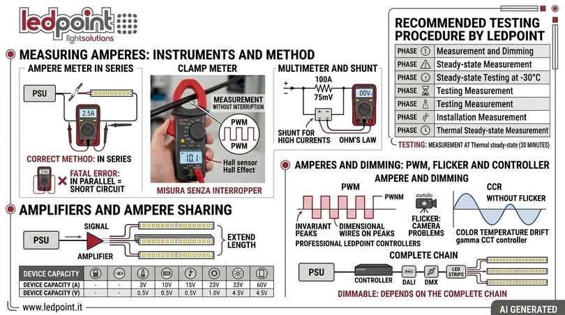
The golden rule is that the ammeter is inserted in series with the circuit, never in parallel: it must have exactly the amps you want to measure flowing through it. Connecting an ammeter in parallel with a load is equivalent to creating a short circuit, with consequences ranging from blowing the instrument's internal fuse to destroying it. To measure the amps drawn by a strip you must therefore break the positive conductor and insert the instrument at the break point.
The clamp meter: measuring amps without breaking the circuit
The clamp meter exploits the very principle discovered by Ampère: it measures the magnetic field generated by the conductor and deduces the amps flowing from it. Current-transformer clamps only work with alternating current, while Hall-effect clamps also measure direct current and are therefore the only ones usable on the low-voltage side of LED strips. When choosing the instrument, check its resolution, often insufficient below one amp, and its ability to read non-sinusoidal waveforms correctly, such as those produced by PWM dimming.
Multimeter and shunt
The digital multimeter is the most widespread instrument and typically has two current inputs: a protected one for milliamps and one, often up to ten amps, for higher currents. Forgetting the probe in the current input and measuring a voltage is the mistake that destroys more multimeters than any other in the world. For currents above the instrument's range a shunt is used, a calibrated resistor of very low value across which a voltage proportional to the amps is measured, according to the same principle as Ohm's law.
Commissioning procedure recommended by Ledpoint
| Stage | Quantity to measure | Instrument | Expected value | Action if non-compliant |
|---|---|---|---|---|
| 1 | Power supply no-load voltage | Multimeter | 24.0–24.5 V | Adjust trimmer or replace |
| 2 | Steady-state amps at strip input | DC clamp or multimeter | ±10% of calculated | Check actual length and power |
| 3 | Voltage at end of strip | Multimeter | over 95% of nominal | Feed from both ends |
| 4 | Profile temperature after 60 min | IR thermometer | below 55 °C | Improve heat dissipation |
| 5 | Amps drawn upstream at 230V | AC clamp | consistent with power | Check power supply efficiency |
| 6 | Leakage current | Leakage clamp | below 10 mA in total | Split over several RCDs |
The most significant moment of commissioning is measuring the amps at thermal steady state, after at least thirty minutes of continuous operation, because LED resistance and therefore the amps vary with temperature, and cold current draw can differ by as much as five to seven per cent from the real value.
13. Amps and dimming: PWM, flicker and controllers
Dimming changes the amps actually drawn by the strip, but it does so in profoundly different ways depending on the technology used, with significant consequences for light quality, camera compatibility and visual comfort. Understanding what happens to the amps during dimming is essential for anyone designing workplaces, TV studios, shops or healthcare spaces.
PWM dimming: the amps stay the same, the time changes
Pulse-width modulation, or PWM, switches the strip on and off thousands of times a second, varying the ratio between on-time and off-time. During the on-instants the amps are always the nominal one-hundred-per-cent value; the reduction in brightness is achieved by reducing the fraction of time the current flows. The average value of the amps drawn falls in proportion to the duty cycle, so a strip dimmed to fifty per cent draws on average half the amps, but the instantaneous peaks remain unchanged.
This characteristic has two often-overlooked practical implications. The first concerns cables and connectors, which must be sized on peak amps and not average amps. The second concerns flicker: PWM frequencies below three hundred hertz produce flicker that is perceptible to cameras and, in some sensitive individuals, a cause of eye strain and headaches. Professional controllers operate at frequencies between 1 and 25 kHz precisely to eliminate the problem, and the anti-flicker drivers in the Ledpoint range are designed for video and broadcast applications.
Analogue CCR dimming
Constant current reduction, or CCR, works by actually reducing the amps flowing through the LEDs instead of interrupting them cyclically. The advantage is the total absence of flicker; the disadvantage is a slight drift in colour temperature towards warm at very low levels and less linear control below ten per cent. For constant-voltage LED strips, PWM dimming remains the dominant choice, while CCR is typical of constant-current drivers for modules and luminaires.
Dimmable: what it really means
The adjective dimmable applied to an LED strip simply indicates that the LEDs can be dimmed, but real dimmability depends on the complete chain: power supply, controller and control protocol. A constant-voltage strip is always dimmable provided there is a suitable device upstream. The most widespread protocols are 0/1-10 V, DALI, DMX512, TRIAC on the mains side and proprietary 2.4 GHz radio systems. The choice also affects the amps: a dimmer downstream of the power supply must withstand the entire current of the strip, while a dimmable power supply handles the dimming internally and imposes no additional current limits on the output side.
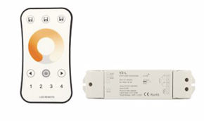
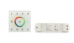
In the Ledpoint catalogue this distinction is reflected in two product families: controllers and dimmers for LED strips, to be chosen by checking that the maximum amps per channel are higher than those of the controlled run, and power supplies with integrated dimmer, which reduce the number of components and simplify wiring. For tunable white strips, the range of CCT controllers manages two independent channels, each with its own amperage limit.
Signal amplifiers and distribution of amps
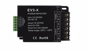
When the total power exceeds the current capacity of a single controller, signal amplifiers are used: devices that replicate the received command while driving a new dedicated power supply. The amplifier does not increase the available amps: it draws them from an additional power supply and modulates them in sync with the input signal, making it possible to extend the length of the installation indefinitely while maintaining uniform dimming.
| Device | Typical amps available per channel | Maximum load at 12V | Maximum load at 24V | Application |
|---|---|---|---|---|
| Compact single-channel dimmer | 4 A | 48 W | 96 W | Furniture, mirrors |
| Standard single-channel dimmer | 8 A | 96 W | 192 W | Residential coves |
| Two-channel CCT controller | 2 × 5 A | 120 W | 240 W | Tunable white |
| RGBW controller | 4 × 4 A | 192 W | 384 W | Scenic effects |
| Signal amplifier | up to 12 A | 144 W | 288 W | Extending long runs |
14. Amps, amp-hours and battery power
Installations in the marine, motorhome, mobile furniture and emergency lighting sectors require you to think in terms of autonomy, and this is where a quantity that is constantly confused with amps comes into play: the amp-hour.
What unit of measurement is Ah
The ampere-hour, symbol Ah, measures the charge capacity of a battery and corresponds to the product of the amps delivered and the hours of delivery. It is not strictly an International System unit, but a convenient practical unit: one ampere-hour equals 3,600 coulombs. Saying that a battery has 10 Ah does not mean it delivers ten amps, but that it can deliver a current whose product with time reaches ten. Similarly, 2 Ah indicates a modest capacity typical of a portable power tool pack, while 100 Ah characterises a motorhome leisure battery.
Calculating the battery autonomy of an LED strip
The procedure is straightforward: calculate the amps drawn by the strip at the battery voltage, divide the capacity in amp-hours by that value, and apply a utilisation factor that accounts for the permitted depth of discharge and efficiency.
| Battery | 12V strip 4.8 W/m × 3 m | Amps drawn | Theoretical autonomy | Real autonomy (DoD 50%) |
|---|---|---|---|---|
| 7 Ah lead-acid | 14.4 W | 1.20 A | 5.8 h | 2.9 h |
| 18 Ah lead-acid | 14.4 W | 1.20 A | 15.0 h | 7.5 h |
| 50 Ah AGM | 14.4 W | 1.20 A | 41.7 h | 20.8 h |
| 100 Ah lithium LiFePO4 | 14.4 W | 1.20 A | 83.3 h | 66.7 h (DoD 80%) |
Lithium batteries allow much greater depths of discharge and keep the amps delivered more constant until the end of the cycle, while lead-acid batteries are subject to Peukert's law, according to which effective capacity decreases as the discharge current increases. For this reason, in marine and motorhome applications, adopting 24-volt strips with a dedicated converter halves the amps drawn from the battery and significantly improves overall autonomy.
Measuring the amps of a battery
To find out the state of health of a battery, measuring the no-load voltage is not enough: you need to measure the amps under load. Dedicated instruments apply a calibrated load and assess the voltage sag, deducing the internal resistance from it. An increase in internal resistance, measurable indirectly through the amps, is the first sign of degradation and results in a reduced ability to deliver sufficient amps during demand peaks, exactly the condition that occurs when several lighting runs are switched on simultaneously.
15. Four professional profiles, four approaches to amps
The same physical quantity takes on different operational meanings depending on who uses it. In this section we have gathered the questions most frequently asked by four distinct professional figures, with the answers Ledpoint's technical service usually provides. It is a way of checking whether the notions set out so far stand up to the test of real cases.
The electrical engineer: designing safely
Whoever signs off a project needs values that can be defended at inspection. The recurring question concerns the correct calculation of the design amps of a linear lighting circuit and coordination with protection devices.
How to calculate the design amps for an LED circuit
The amperage calculation must be carried out on three levels. First level, extra-low-voltage side: amps of each run equal to the run's power divided by the voltage, increased by thirty per cent. Second level, power supply input side: input power equal to output power divided by efficiency, typically 0.88–0.93 for quality power supplies, then divided by the mains voltage and the power factor. Third level, switchboard: sum of the amps of all power supplies, applying the diversity factor and checking discrimination with upstream protection devices.
How amps affect the safety of the installation
Amps remain the parameter on which the entire electrical safety chain rests. Overload protection requires the device's rated amps to lie between the design amps and the cable's current capacity; short-circuit protection requires the let-through energy to be lower than that the conductor can withstand; protection of people depends on the thirty milliamps of the RCD. An installation in which the amps have been calculated correctly is by construction a safe installation, because every component works within its own thermal domain.
Applicable regulations
The primary reference remains CEI 64-8 for low-voltage user installations, supplemented by UNI EN 12464-1 for the lighting requirements of indoor workplaces and by IEC 60598 for luminaires. For SELV (safety extra-low voltage) circuits, the category that includes 12 and 24-volt installations, the standard requires separation from higher-voltage circuits and prohibits earthing of live parts.
The installer: reading specifications correctly
How to determine the amps needed for a new installation
The process is the one described in chapter seven, applied run by run. The most useful practical advice is to fill in a design table with one row per run, showing length, watts per metre, total watts, nominal amps, increased amps, cable section and assigned power supply. This table, attached to the documentation handed over to the customer, is worth more than any commercial guarantee, because it shows that the sizing was calculated and not guessed.
What are the risks of overloading a circuit
Exceeding the amps allowed by the design produces cascading effects: heating of the copper tracks with possible PCB delamination, accelerated ageing of the LEDs, tripping of the power supply protection with cyclic flashing, degradation of cable insulation, melting of plastic connectors. Current overload rarely causes immediate failure: it causes progressive degradation that shows up months later, when the installer is long gone and responsibility is hard to assign.
What is the current limit for standard cables
See the current capacity table in chapter ten. The practical summary for LED strip installers is this: 0.75 mm² up to five amps on short runs, 1.5 mm² up to ten amps, 2.5 mm² beyond. When in doubt it is always worth going up one size: the extra cost of copper is negligible compared with the cost of a warranty call-out.
The automation designer: integrating amps into home automation
How to integrate current data into automation projects
Modern home automation systems make it possible to monitor in real time the amps actually drawn by each circuit using DIN-rail metering modules or integrated Hall-effect sensors. The amperage figure thus becomes a diagnostic indicator: an abnormal change in amps on a lighting line typically signals the failure of a segment, oxidation of a contact or degradation of a power supply, long before the problem is visible to the naked eye.
How to ensure current limits are respected
The most effective strategy is to program alarm thresholds at supervisor level: if the amps measured on a line exceed the design value plus ten per cent, the system generates a notification. At higher levels, load-shedding logic can be implemented that progressively dims the less critical zones to keep total consumption within the available power. Integration with presence and daylight sensors completes the picture, reducing the amps drawn during low-occupancy periods.
How to reduce consumption while complying with standards
The main lever is the luminous efficacy of the source: moving from a 100 lm/W strip to a 155 lm/W one reduces the amps needed to obtain the same flux by more than a third. The second lever is automatic dimming according to daylight, which in installations with glazed façades can cut annual consumption by thirty or forty per cent. The third is the choice of system voltage: for the same lumens delivered, a 24 or 48-volt system loses much less energy in the conductors than a 12-volt one, simply because the circulating amps are lower and losses grow with the square of the current.
The business owner: differentiating the offer
How to train the team on current-related issues
Ledpoint's experience suggests a three-module approach: a theory module of a few hours on the relationships between amps, volts and watts and on Ohm's law; a practical measurement module with multimeter and clamp on demonstration benches; a guided design module filling in sizing tables. Competence with amps is the single factor that most affects the warranty call-back rate of an installation company.
How to stand out from the competition
Differentiation comes through the documentation delivered. A company that attaches to its quote the amperage calculation for each run, the cable sections adopted, the voltage drop check and the commissioning report with actual measurements conveys a level of professionalism the customer perceives immediately, even without understanding the technical details. It is the same logic by which Ledpoint always declares measured rather than theoretical values: transparency about the numbers is a competitive advantage.
The challenges of high-current installations
In large commercial installations, the total amps required on the low-voltage side easily reach the hundreds. The main critical issues concern copper distribution, coordination of protection devices, thermal management of switchboards housing dozens of power supplies, and maintainability. The design answer is to decentralise: many medium-sized power supplies distributed close to the loads, rather than a few large power supplies concentrated in a single point, reduce the amps transported, cut cable sections and limit the extent of any fault.

16. Regulations, standards and industry manuals
Every technical statement in this guide is backed by a well-established body of standards. Below we list the main references, useful both for further study and for drafting correct specifications.
| Reference | Subject | Relevance to amps |
|---|---|---|
| CEI 64-8 | Low-voltage electrical user installations | Permissible amps in conductors, protection devices, SELV circuits |
| CEI-UNEL 35024 | Cable current-carrying capacity in continuous service | Official tables of permissible amps for each cross-section |
| UNI EN 12464-1 | Lighting of indoor workplaces | Illuminance levels that determine power and therefore amps |
| IEC 60598 | Luminaires: general requirements | Thermal tests in amps and electrical safety |
| IEC 62386 | DALI protocol for digital control | Dimming management and therefore average amps drawn |
| EN 61347 | Control gear for light sources | Construction requirements for power supplies and output amps |
| EN 55015 | Electromagnetic compatibility of lighting equipment | Emissions related to switched amps |
| IEC 62471 | Photobiological safety | Risk groups as a function of radiance |
| IEC 60529 | Degrees of protection provided by enclosures (IP code) | Environmental conditions affecting current derating |
| EU Regulation 2019/2020 | Ecodesign of light sources | Minimum efficacy requirements in lumens per watt |
For metrological details the definitive reference remains the International System brochure published by the BIPM, while for the history of electrodynamics the entry on André-Marie Ampère is useful. On the lighting side, the manuals of the Commission Internationale de l'Éclairage form the scientific basis of most European standards.
17. Ledpoint in-house tests: laboratory-measured data
The following tables show measurements taken in Ledpoint's Faenza laboratory on production samples, with standard power supplies and calibrated instruments. They are proprietary data, not available elsewhere, and serve to quantify how far the actually measured amps deviate from the theoretical ones under real operating conditions. All current measurements were taken after sixty minutes of continuous operation, at an ambient temperature of twenty-four degrees, with a stabilised supply voltage.
Deviation between theoretical and measured amps
| Sample | Calculated theoretical amps | Cold amps | Steady-state amps | Deviation |
|---|---|---|---|---|
| Strip 24V 9.6 W/m × 5 m | 2.000 A | 2.08 A | 1.96 A | -2.0% |
| Strip 24V 14.4 W/m × 5 m | 3.000 A | 3.14 A | 2.91 A | -3.0% |
| Strip 24V 19.2 W/m × 5 m | 4.000 A | 4.22 A | 3.85 A | -3.8% |
| COB strip 24V 16 W/m × 5 m | 3.333 A | 3.48 A | 3.24 A | -2.8% |
| Strip 12V 14.4 W/m × 5 m | 6.000 A | 6.31 A | 5.74 A | -4.3% |
| Strip 48V 14.4 W/m × 10 m | 3.000 A | 3.09 A | 2.95 A | -1.7% |
The most interesting finding is counter-intuitive: the amps measured at steady state are lower than the theoretical ones, not higher. The reason is the voltage drop along the strip, which reduces the voltage actually applied to the LEDs in the final section and therefore the amps drawn by those segments. An installation that "consumes less than expected" is not more efficient: it is simply producing less light in the final portion. The phenomenon is more pronounced at twelve volts, where the amps involved are double, and almost negligible at forty-eight volts.
Temperature as a function of amps per metre and mounting surface
| Configuration | Amps per metre | PCB temperature after 60 min | Delta over ambient | Estimated useful life |
|---|---|---|---|---|
| 14.4 W/m strip bare on plasterboard | 0.60 A/m | 68 °C | +44 °C | about 25,000 h |
| 14.4 W/m strip in recessed aluminium profile | 0.60 A/m | 52 °C | +28 °C | about 40,000 h |
| 14.4 W/m strip in surface-mounted aluminium profile | 0.60 A/m | 46 °C | +22 °C | over 50,000 h |
| 19.2 W/m strip bare on plasterboard | 0.80 A/m | 81 °C | +57 °C | less than 15,000 h |
| 19.2 W/m strip in surface-mounted aluminium profile | 0.80 A/m | 54 °C | +30 °C | about 40,000 h |
| 19.2 W/m strip dimmed to 70% in profile | 0.56 A/m | 42 °C | +18 °C | over 60,000 h |
The comparison between the first and last rows sums up this whole guide: the same amount of light, obtained with intelligent current management and a heat-sinking profile, more than doubles the useful life of the installation. This is why Ledpoint consistently recommends pairing strip and profile, also available in a complete version with diffuser and end caps.
Light uniformity and amps as a function of feed topology
| Topology | Length | Input amps | Lux at 0 m | Lux at end of run | Uniformity |
|---|---|---|---|---|---|
| Single-end feed | 5 m | 3.00 A | 412 | 398 | 96.6% |
| Single-end feed | 10 m | 6.00 A | 412 | 348 | 84.5% |
| Double-end feed | 10 m | 3.00 A per end | 410 | 396 (at centre) | 96.6% |
| Single-end feed | 15 m | 9.00 A | 411 | 288 | 70.1% |
| Injection every 5 m | 15 m | 3.00 A per point | 410 | 395 | 96.3% |
The reading is immediate: reducing the amps flowing through each individual section of PCB is the most effective way to obtain a uniform line of light, and the threshold of visual perceptibility of non-uniformity, which lies around eighty-five per cent, is crossed precisely when the product of amps and metres exceeds thirty.
18. The ten most common mistakes about amps
An analysis of the support requests received by our technical service reveals a surprisingly repetitive pattern. Here it is, in decreasing order of frequency, with the corresponding countermeasure.
| # | Mistake | Consequence | Countermeasure |
|---|---|---|---|
| 1 | Power supply chosen on exact watts, with no margin on amps | Overheating and early failure | Minimum 30% margin on amps |
| 2 | Long strip fed from one end only | Voltage drop and non-uniformity | Double-end feeding or injection points |
| 3 | Cable section calculated on thermal capacity only | Excessive drop at extra-low voltage | Also check the drop with real amps |
| 4 | Quick connectors on high currents | Contact heating and melting | Soldering above 3 amps |
| 5 | Confusing amps with amp-hours of capacity | Overestimated battery autonomy | Distinguish current from capacity |
| 6 | 12V power supply on a 24V strip or vice versa | Dim light or immediate destruction | Check voltage before amps |
| 7 | Too many power supplies on one circuit breaker | Tripping due to inrush current | Curve C and splitting circuits |
| 8 | IP67 power supply loaded to 100% of its amps | Thermal derating not considered | Limit to 70% of rated current |
| 9 | Outputs of two power supplies connected in parallel | Current imbalance and failure | Separate runs, common negatives |
| 10 | Dimmer sized on average instead of peak amps | Controller overheating | Size on PWM peak value |
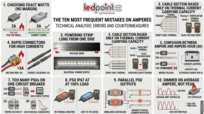
19. On-site operational checklist
This sequence of checks can be printed and used as a control form. It is designed to be completed in less than ten minutes for each installation run and covers the entire project life cycle, from sizing to final commissioning.
| Stage | Check | Acceptance criterion |
|---|---|---|
| Design | Power per metre taken from data sheet | Measured value declared by the manufacturer |
| Design | Length rounded to usable cut | Multiple of the cutting interval |
| Design | Nominal amps calculated with I = P / V | Calculation documented per run |
| Design | Margin applied to amps | At least 20%, preferably 30% |
| Design | Product of amps and metres | Below 30 for 2 oz copper |
| Design | Cable section on capacity and drop | Drop below 3% of voltage |
| Supply | Power supply rated current | Higher than increased amps |
| Supply | IP rating consistent with environment | IP65 or higher outdoors |
| Supply | Dimmer with adequate amps per channel | Higher than peak current |
| Installation | Heat-sinking profile installed | Continuous thermal contact |
| Installation | Soldered joints above 3 amps | Heat-shrink sleeving applied |
| Installation | Polarity respected on each branch | Red positive, black negative |
| Installation | Common negatives between power supplies | Positives strictly separate |
| Commissioning | No-load output voltage | Within 2% of nominal |
| Commissioning | Amps measured at steady state | Within 10% of calculated |
| Commissioning | Voltage at end of run | Over 95% of nominal |
| Commissioning | Profile temperature | Below 55 °C |
| Commissioning | Total leakage current | Below 10 mA |
| Handover | Amps-per-run table attached | Signed and dated |
| Handover | Wiring diagram handed over | With protection devices indicated |
20. Electrical engineering glossary
| Term | Operational definition |
|---|---|
| Ampere (A) | SI unit of electric current, equal to one coulomb flowing per second. |
| Ampere-hour (Ah) | Charge capacity of a battery, equal to the product of amps delivered and hours of delivery. |
| Ammeter | Instrument that measures amps; it must always be inserted in series with the circuit. |
| Amperage | Colloquial term for the current value in amps of a device or circuit. |
| Voltage drop | Loss of voltage along a conductor, equal to the product of amps and the conductor's resistance. |
| Coulomb (C) | Unit of electric charge, equal to one ampere for one second. |
| CRI (Ra) | Colour rendering index, measures how faithfully a source renders colours. |
| Derating | Reduction of usable amps as a function of operating temperature. |
| Duty cycle | Fraction of time during which current flows in a PWM modulation cycle. |
| Joule effect | Heat dissipation in a conductor, proportional to the square of the amps. |
| Power factor | Ratio between active power in watts and apparent power in volt-amperes. |
| IP rating | Classification of enclosure protection against solid objects and liquids. |
| Inrush current | Current peak at switch-on, caused by the charging of capacitors. |
| Kelvin (K) | Unit of the correlated colour temperature of a light source. |
| L70 | Number of hours after which luminous flux falls to seventy per cent of its initial value. |
| Ohm's law | Relationship between voltage, current and resistance: V = R × I. |
| Luminance | Luminous intensity per unit of apparent surface, measured in candelas per square metre. |
| Lux (lx) | Unit of illuminance, equal to one lumen per square metre. |
| Milliampere (mA) | One thousandth of an ampere; 1,000 mA equal 1 A. |
| Ohm (Ω) | Unit of electrical resistance; one ohm lets one ampere through under one volt. |
| PWM | Pulse-width modulation, a dimming technique that varies the current conduction time. |
| Ripple | Residual fluctuation of the output voltage or current of a power supply. |
| SELV | Safety extra-low voltage, a category that includes 12 and 24-volt circuits. |
| Shunt | Calibrated resistor used to measure high currents via the voltage drop across it. |
| Volt-ampere (VA) | Unit of apparent power, the product of RMS volts and amps. |
| Watt (W) | Unit of power, equal to the product of volts and amps in direct current. |
21. Frequently asked questions about amps
We have collected the thirty-six questions we are asked most often about amps and their role in LED strips. Each answer is concise and immediately applicable: click on a question to open the answer.
| Question |
|---|
What does 1 amp correspond to?One ampere corresponds to one coulomb of electric charge per second flowing through the cross-section of a conductor, i.e. about 6.241 × 10¹⁸ electrons every second. In practice, one amp is the current drawn by 24 watts of LED strips at 24 volts, or by 12 watts at 12 volts. |
How many watts is 1 amp?One amp is not equivalent to a fixed number of watts: it depends on the voltage. One amp equals 12 watts at 12 volts, 24 watts at 24 volts, 48 watts at 48 volts and 230 watts at 230 volts. The formula to apply is always watts equal volts multiplied by amps. |
How many amps is 1 kW?One kilowatt corresponds to about 4.35 amps on a 230-volt single-phase supply and about 1.44 amps per phase on a 400-volt three-phase supply. On the low-voltage side of LED strips, one kilowatt requires 41.67 amps at 24 volts and as much as 83.33 amps at 12 volts. |
How many kW is 1 amp?One amp at 230 volts corresponds to 230 watts, i.e. 0.23 kilowatts. At 24 volts one amp is worth only 24 watts, i.e. 0.024 kilowatts. Converting between amps and kilowatts always requires knowing the circuit voltage, because they are physically different quantities. |
How many amps is 220 volts?The question has no direct answer: volts indicate voltage, amps indicate current. On a 220–230 volt line, the amps depend on the connected load. A 1,000-watt load draws about 4.35 amps, while a 3 kW domestic contract allows draws of up to about 13 amps. |
What is amperage used for?Amperage is used to size every component of an installation: cable section, power supply size, fuses, circuit breakers and connectors. In LED strips, amps also determine voltage drop, heating of the copper tracks and the actual lifespan of the LED chips. |
What is the difference between volts and amps?Volts measure the potential difference, i.e. the push that sets charges in motion; amps measure how many charges actually move. In the hydraulic analogy volts are the pressure and amps the flow rate. Voltage must be matched exactly, while available amps can be generous. |
What is the difference between watts and amps?The watt measures power, the ampere measures current. They are linked by the relationship watts equal volts times amps, so the same power corresponds to very different amps at different voltages: 120 watts are ten amps at 12 volts and five amps at 24 volts. |
What is measured in amps?Amps measure the intensity of electric current, i.e. the amount of charge flowing through a cross-section of conductor per unit of time. Power, expressed in watts, and battery capacity, expressed in amp-hours, are not measured in amps. |
What did Ampère discover?André-Marie Ampère showed in 1820 that two parallel current-carrying conductors attract or repel each other depending on the direction of the currents, founding electrodynamics. The law that bears his name links the strength of the magnetic field to the amps flowing through the conductor generating it. |
How do you calculate amps?Amps are calculated by dividing power in watts by voltage in volts, according to the formula I = P / V. Alternatively, knowing resistance and voltage, you apply Ohm's law in the form I = V / R. For LED strips the first formula is the correct one. |
How do you calculate the amps of an LED strip?Multiply the power per metre by the metres installed to get total watts, then divide the result by the system voltage. Add a thirty per cent margin to the value obtained. Example: 14.4 W/m times 5 m gives 72 W, which at 24 V corresponds to 3 amps. |
How do you measure amps?Amps are measured with an ammeter inserted in series with the circuit, or with a clamp meter that reads the magnetic field without breaking the conductor. For the direct current of LED strips you need a Hall-effect clamp, because current-transformer clamps only work with alternating current. |
How many amps can a 1.5 mm² cable carry?A 1.5 mm² copper conductor can carry about 17 amps in free air and about 13 amps in conduit or trunking. In extra-low-voltage installations, however, the real limit is set by voltage drop, which significantly reduces the amps that can be carried over long runs. |
What does 30 mA correspond to?Thirty milliamps correspond to 0.03 amps and it is the tripping threshold of the high-sensitivity residual current device. It is a tiny current, invisible in terms of power, but enough to cause ventricular fibrillation: this is why electrical safety is decided in milliamps. |
What unit of measurement is Ah?The amp-hour measures the charge capacity of a battery and corresponds to the amps delivered multiplied by the hours of delivery. A 10 Ah battery can supply one amp for ten hours or ten amps for one hour, with corrections due to efficiency and depth of discharge. |
What does 10 amps mean?Ten amps indicate a current of ten coulombs per second. On a 230-volt domestic line ten amps correspond to 2,300 watts; on the low-voltage side of a 24-volt LED installation, the same ten amps supply 240 watts, i.e. about sixteen metres of 14.4 W/m strip. |
How many amps does household electricity have?The standard Italian 3 kW domestic contract allows draws of up to about 13–14 amps at 230 volts, with a main circuit breaker typically rated 16 A or 20 A. Individual lighting circuits are protected at 10 amps and socket circuits at 16 amps. |
What is the unit of measurement of electric current?The unit of measurement of electric current is the ampere, symbol A, one of the seven base units of the International System. Since 2019 the ampere has been defined by fixing the value of the elementary charge at 1.602176634 × 10⁻¹⁹ coulombs, making it reproducible in any laboratory. |
What is the symbol for the ampere?The symbol for the ampere is a capital letter A, with no full stop and no plural form: you write 5 A. Abbreviations such as amp or amper are jargon and should not be used in technical documentation, specifications or product data sheets. |
How many amps are needed for 100 watts?One hundred watts require 4.17 amps at 24 volts, 8.33 amps at 12 volts, 2.08 amps at 48 volts and about 0.43 amps at 230 volts. It is the clearest demonstration of the advantage of higher voltages: the higher the voltage, the fewer amps are needed for the same power. |
How many amps does a 5-metre reel draw?A 5-metre reel at 24 volts draws 1 amp at 4.8 W/m, 2 amps at 9.6 W/m, 3 amps at 14.4 W/m and 4 amps at 19.2 W/m. At 12 volts the amps exactly double for the same installed power. |
Why are amps important in LED strips?Because the copper tracks of an LED strip have a tiny cross-section, in the order of 0.07–0.21 mm². The amps flowing through them determine voltage drop, heating of the printed circuit and light non-uniformity between the start and end of the run. |
How many amps can an LED strip carry?It depends on the copper thickness: about 2.5 amps for 1-ounce copper, 5 amps for 2-ounce and 7.5 amps for 3-ounce. Exceeding these values causes the tracks to overheat and accelerates lumen depreciation. |
How do you avoid voltage drop in LED strips?By reducing the amps flowing through the PCB. The three effective techniques are feeding from both ends, injecting current via a parallel cable every five metres, and segmenting the installation into independent runs with dedicated power. |
Is 12V or 24V better for LED strips?For the same power, 24 volts require half the amps of 12 volts, so they reduce cable losses by a factor of four, halve voltage drop and double the length that can be fed from one end. 12 volts remain suitable only where a twelve-volt infrastructure already exists. |
How do you choose a power supply based on amps?Calculate the amps of the load, add a thirty per cent margin and choose a power supply with an equal or higher rated output current. Always also check the installation temperature, because thermal derating reduces the amps that can actually be delivered. |
Can two power supplies be connected in parallel?The outputs of two standard power supplies must not be connected in parallel, because minimal voltage differences would cause imbalances in the amps delivered. The correct solution is to assign each power supply its own strip run, sharing only the negative conductors. |
Does dimming reduce the amps drawn?With PWM dimming the peak amps remain nominal, while the average value falls in proportion to the duty cycle. Cables, connectors and controllers must therefore be sized on peak amps and not average amps, to avoid overheating. |
What is inrush current?It is the current peak that occurs at switch-on, when the power supply's input capacitors are discharged. It can reach tens of amps for a few milliseconds and, with many power supplies switched on together, can trip the circuit breaker even with modest loads. |
What is the difference between constant voltage and constant current?In constant-voltage devices the voltage is fixed and the amps depend on the load: this is the case with 12, 24 and 48-volt LED strips. In constant-current devices it is the current in amps that is fixed by the driver, while the voltage adapts to the connected load. |
How do you measure the amps of a battery?You don't measure a battery's amps in absolute terms: you measure the amps it delivers under a defined load, or its capacity in amp-hours. An increase in internal resistance reduces the amps available during demand peaks and is the first sign of degradation. |
What is a volt-ampere?The volt-ampere measures apparent power, i.e. the product of RMS volts and amps, while the watt measures active power actually converted into work. The ratio between the two is the power factor, and switchboards are always sized on apparent power. |
How many metres of LED strip can I connect to a power supply?It depends on the available amps and the power per metre. A 150-watt 24-volt power supply delivers 6.25 amps and, with a thirty per cent margin, supplies about eight metres of 14.4 W/m strip. The maximum length permitted by the PCB must still be checked. |
What is the product of amps and metres used for?It is a practical indicator that sums up the risk of voltage drop. Multiplying the input amps by the metres of the run gives a number that, below twenty, indicates a trouble-free installation; between twenty and thirty suggests double-end feeding; above thirty makes it mandatory. |
Does current in amps affect LED lifespan?Yes, decisively. The amps flowing through each chip determine the power dissipated and therefore the junction temperature, which governs lumen depreciation. Running a more powerful strip dimmed reduces the effective amps and significantly extends its useful life. |
22. Quick reference cards: amps room by room
This section contains twelve concise reference cards, one for each typical linear lighting application. Each card shows the design amps, the increased amps and specific points to watch, so you can go from theoretical calculation to practical decision without rereading the whole manual. The cards were built by applying exactly the six-step procedure described in chapter seven, and current values are always expressed in amps at the stated voltage.
Kitchen: under-cabinet and plinth
A three-metre under-cabinet run at 24 volts with a 9.6 W/m strip: 28.8 watts, 1.20 amps nominal, 1.56 amps with margin. The plinth generally adds another two metres, i.e. 0.80 amps, for a total of 2.00 amps nominal and 2.60 amps design. The amps are modest, but the real constraint is heat: above the hob a heat-sinking profile and a twenty per cent current derating are always recommended.
Bathroom: mirror and niches
A 2.4-metre perimeter mirror with a 4.8 W/m strip at 24 volts: 11.5 watts and just 0.48 amps, which become 0.62 amps with margin. In humid environments the design amps must be paired with an adequate IP rating: with IP65 protection the power supply should be loaded to no more than seventy per cent of its rated amps, because heat dissipation is hampered by the sealed enclosure.
Living room: perimeter cove
Nine metres of 14.4 W/m strip at 24 volts develop 129.6 watts, i.e. 5.40 amps nominal and 7.02 amps design. With 5.40 amps over nine metres the amps-by-metres product is 48.6, well beyond the threshold of thirty: double-end feeding is not just recommended, it is necessary, and it halves the current entering from each end to 2.70 amps.
Bedroom: headboard and false ceiling
A four-metre headboard with a 6 W/m COB strip at 24 volts draws 24 watts, i.e. exactly 1.00 amp, which becomes 1.30 amps with margin. The low amps involved allow 0.5 mm² cables and a compact 30-watt power supply. For night-time dimming, a dimmer with 4 amps per channel is more than sufficient.
Indoor staircase
Fifteen metres of 6 W/m COB strip at 24 volts produce 90 watts, equal to 3.75 amps nominal and 4.88 amps design. The amps-by-metres product is 56, so at least two injection points are needed. Distributing the amps over three feed points every five metres, each section carries just 1.25 amps and uniformity stays above ninety-six per cent.
Hotel corridor
Twenty-five metres at 48 volts with a 14.4 W/m strip: 360 watts and only 7.50 amps nominal, 9.75 amps with margin. At the same power a 12-volt system would have required 30 amps nominal: it is the most effective demonstration of how the choice of voltage governs the amps and, consequently, the entire wiring architecture.
Retail shop window
Twelve metres of 19.2 W/m strip at 24 volts develop 230.4 watts, i.e. 9.60 amps nominal and 12.48 amps design. The high design amps require 2.5 mm² cable, double-end feeding and attention to power supply derating, as it is often installed in closed cavities where the amps actually available fall to eighty per cent of the nameplate value.
Open-plan office
Twenty metres of light slot with a 24 W/m strip at 24 volts require 480 watts, equal to 20.00 amps nominal and 26.00 amps design. When the amps exceed fifteen, the solution is not a bigger power supply but a different topology: two ten-metre runs with independent feeds reduce the amps per run to ten and drastically simplify the wiring.
Custom furniture and fittings
One and a half metres of 4.8 W/m strip at 12 volts draws 7.2 watts, i.e. 0.60 amps nominal and 0.78 amps with margin. The amps involved are minimal, but cables are often very thin and joints numerous: it is precisely in low-current applications that poor-quality connectors cause the most failures, due to contact resistance.
Outdoor and façades
Outdoor installations combine high amps with harsh environmental conditions. A ten-metre band with a 14.4 W/m IP67 strip at 24 volts requires 6.00 amps nominal and 7.80 amps design, but the summer temperature inside a profile exposed to the sun can reduce the amps the waterproof power supply can deliver by twenty-five per cent.
Marine and motorhome
On board, the available voltage is typically 12 volts, so the amps required double compared with an equivalent domestic installation. Three metres of 4.8 W/m strip draw 1.20 amps and, on a 100 Ah lithium battery, guarantee over sixty hours of autonomy. Here, reducing the amps drawn is a matter of autonomy even before safety.
Museum and premium retail lighting
In these environments amps must be dosed and managed with an eye to light quality: high-CRI strips run in derating are preferred, i.e. with amps below the maximum permitted, to contain junction temperature and stabilise colour temperature over time. A thirty per cent reduction in amps can extend useful life beyond sixty thousand hours.
Summary of amperage formulas
| Goal | Formula | Example |
|---|---|---|
| Amps from power and voltage | I = P / V | 72 W / 24 V = 3.00 amps |
| Amps from voltage and resistance | I = V / R | 24 V / 8 Ω = 3.00 amps |
| Amps from power and resistance | I = √(P / R) | √(72 / 8) = 3.00 amps |
| Design amps | Idesign = I × 1.3 | 3.00 × 1.3 = 3.90 amps |
| Watts from amps | P = V × I | 24 V × 3 A = 72 watts |
| Cable drop | ΔV = 2 ρ L I / S | 5 amps, 10 m, 1 mm² = 1.78 V |
| Drop along the strip | ΔV = Rtot Itot / 2 | 6 amps over 10 m = about 2.5 V |
| Amps-by-metres index | K = I × L | 6 amps × 10 m = 60 (critical) |
| Battery autonomy | h = Ah / I | 100 Ah / 1.2 amps = 83 hours |
| Mains-side amps | I = P / (V × PF × η) | 150 W at 230 V = about 0.75 amps |
Ten formulas, one single concept: any linear lighting problem can be solved by bringing everything back to amps and checking that every component in the chain can handle at least thirty per cent more than is actually needed. It is a simple, repeatable and verifiable discipline, and it clearly distinguishes a designed installation from an improvised one.
23. Amps as the common language of the project
Having reached the end of this journey, one thing should be clear: amps are not a technical detail reserved for specialists, but the common language through which all the components of an LED lighting installation communicate. The strip speaks in amps when it declares its power per metre; the cable speaks in amps when it declares its current capacity; the power supply speaks in amps when it declares its output current; the fuse, the circuit breaker and the RCD speak in amps when they declare their tripping threshold. Translating everything into this single quantity means being able to verify the consistency of the whole system with a spreadsheet and five minutes of attention.
The second message worth taking away concerns the relationship between amps and time. An overloaded installation doesn't fail tomorrow: it fails in two years' time, when the client has long forgotten who installed what and all they remember is that the light "didn't last". Every amp saved thanks to a higher voltage, a larger cable section, a heat-sinking profile or intelligent derating is a direct investment in the useful life of the installation, and therefore in the reputation of whoever built it.
The third message is methodological. Calculating amps takes one division, one multiplication and one margin: three operations any professional can carry out in thirty seconds. Not doing them is a choice, not an oversight. The configurator on this page, the watts, volts and amps conversion tables and the on-site checklist were designed precisely to make those thirty seconds even faster and to remove every excuse.
To turn these principles into a concrete project, the Ledpoint catalogue offers the entire supply chain: professional LED strips with real, declared and measured power, product lines selected for performance, power supplies sized in amps, heat-sinking aluminium profiles and control and dimming systems. Those wishing to learn more about sizing the power supply will also find useful our complete technical guide to 12V power supplies and the in-depth article on indirect lighting with LED strips and profiles. Ledpoint's technical service is available to check the amperage calculations of any project free of charge, from custom furniture to retail installations of hundreds of metres.
This article was developed with the support of artificial intelligence and subsequently reviewed, corrected and validated by the Ledpoint.it technical team, which guarantees its reliability and compliance with official sources.