







Car LEDs: 12V battery and LED strips – complete guide
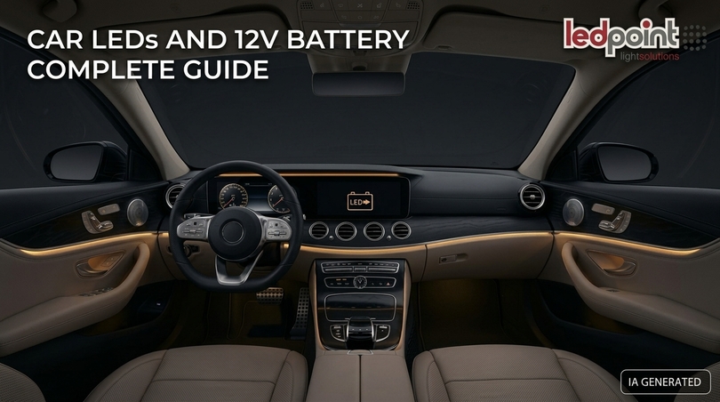
The 12V battery problem in cars with LED strips is today one of the most widespread and least understood critical issues in the entire automotive lighting sector. Thousands of drivers, camper van owners, van converters, and professional installers face the same scenario every day: an automotive LED strip installed with enthusiasm that, after a few weeks, lights up unevenly, changes its white tone, loses intensity towards the end of the tape, or (in the worst-case scenario) leaves the vehicle with a completely dead battery in the morning. The superficial diagnosis is almost always the same and almost always wrong: "the battery is old". The technical reality is very different, and it concerns three precise, measurable, and solvable electrical phenomena: voltage drop along the strip's printed circuit board, onboard voltage instability in 12V vehicles, and parasitic drain generated by incorrect wiring.
This guide is born to definitively close the matter. It is not a list of generic tips copied from forums, but an operational manual built on real measurements, verifiable formulas, conversion tables, wiring diagrams, regulatory references, and replicable installation procedures. Inside you will find the method to understand why your automotive LED system has a problem, how to measure it with a multimeter in less than ten minutes, and how to solve it at the root using the technology that today represents the state of the art for on-vehicle applications: the constant current control COB LED strip.
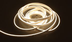
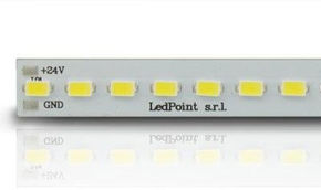
The product around which the entire application part of this guide revolves is the COB LED strip 10m white 4000K CRI Ra>93 384led/m 12V 8.6W/m PCB 5mm constant current control by Ledpoint.it, a solution designed precisely to eliminate the problem of voltage drop and onboard network fluctuations. We will explain, step by step, how to install it, with which accessories, with which cable gauges, with which protections, and with which electrical diagrams, because the right product installed poorly remains a problem, while the right product installed well becomes a definitive solution.
In this article...
1. The real problem: why the 12V battery drains with LED strips
When a customer walks into the workshop saying "ever since I installed LED strips, my battery keeps draining", in the vast majority of cases the battery is perfectly healthy. The problem is upstream, and it stems from a technical misunderstanding that the entire consumer market has fueled for years: an LED strip designed for stabilized 12V domestic lighting is not an LED strip designed for automotive use. They are two different electrical worlds, with different requirements, and treating them as equivalent produces exactly the faults we are about to analyze.
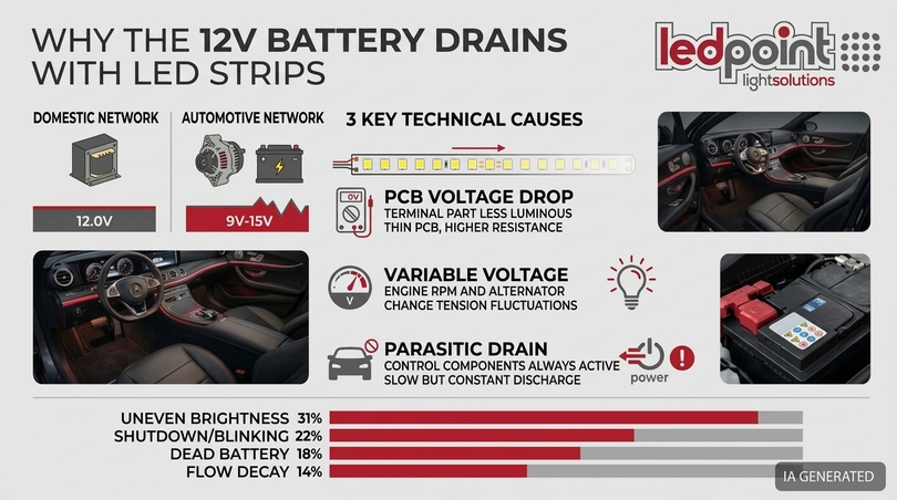
In the domestic world, a 12V strip is powered by a switching power supply that delivers 12.0V ± 0.2V, with contained ripple and no significant transients. In the automotive world, the same strip is connected to a network that oscillates between 9V and 15V under normal conditions, which undergoes much higher peaks under abnormal conditions, which presents residual ripple due to the rectification of the alternator, and which must coexist with dozens of electronic control units. The result is that the strip almost always operates outside its design point: either under-powered, and then it is dim and weak, or over-powered, and then it consumes much more than expected, heats up, degrades, and drains the battery.
Added to this is the second phenomenon, the one that generates the classic "fade-out effect": the voltage drop along the copper traces of the strip. The longer the strip, the more current must flow through the first meter of copper to power all the subsequent meters, and the more voltage is lost along the way. On a traditional 12V strip, beyond 5 meters the phenomenon becomes so marked that the last portion is visibly darker and warmer in tone. The average user, to compensate, raises the voltage or doubles the strips, and in doing so also doubles the consumption: from here to a dead battery the step is very short.
The three technical causes, separated one by one
To solve a problem you must first dismantle it into its components. In the case of automotive LED strips, the causes of the "draining battery" are three, and they must be addressed in sequence because they amplify each other. Whoever solves only one gets a partial improvement destined not to last.
| Cause | Physical phenomenon | Perceived effect | Impact on battery | Structural solution |
| Voltage drop on PCB | Resistance of copper traces multiplied by the current flowing through them | Dark end of the strip, shifted color, uneven brightness | Indirect: pushes to oversize the system | Constant current control strip |
| Variable onboard voltage | Alternator and regulator bring the network to 13.8–14.8V with engine running | Brighter light with engine running, drop with engine off | Direct: consumption up to +60% compared to nominal | On-strip regulation electronics |
| Parasitic drain | Connection to permanent positive and controller standby | Dead battery after days of parking | Direct and cumulative: even 20–80 mA continuous | Ignition-switched power, relay, disconnect switch |
The difference between an automotive LED lighting system that lasts ten years and one that dies in three months lies entirely in the management of these three variables. Everything else (color, design, profile, diffuser) comes after.
How widespread the problem is: industry numbers
The aftermarket for vehicle LED lighting has grown exponentially in recent years, driven by three parallel phenomena: the spread of van life and camper van conversions, the growth of the fitted commercial vehicle segment (mobile workshops, refrigerated vans, food trucks, rescue vehicles), and the trend of interior ambient lighting on standard cars. The volume of installations has grown much faster than the average technical competence of those installing them, and this explains why technical forums are saturated with reports of strips that turn off during startup, fade out, burn out, or drain the battery.
| Type of complaint on automotive LED strip installations | Estimated incidence on reports | Representation |
| Uneven brightness / dead end of the strip | about 31% | ███████████████ |
| Strip turns off or flickers during startup | about 22% | ███████████ |
| Dead battery after prolonged parking | about 18% | █████████ |
| Premature lumen depreciation / color shift | about 14% | ███████ |
| Adhesive peeling, water ingress, vibration breakage | about 9% | ████ |
| Radio interference, dashboard warnings, ECU errors | about 6% | ███ |
Indicative values derived from the qualitative analysis of the most frequent assistance cases in the automotive aftermarket lighting sector: they serve to order intervention priorities, not as official statistics.
The most significant fact is that over half of the reports concern phenomena attributable to voltage and current management, not diode defects. In other words: the LED itself is almost never the culprit. The culprit is the electrical architecture of the strip and the way it was connected to the onboard network.
2. The car's 12V electrical system is (almost never) at 12V
The label "12-volt system" is a commercial convention, not a physical description. The actual voltage at the terminals of a vehicle varies constantly depending on the state of charge, temperature, engine speed, connected loads, and the state of the alternator. Designing or installing lighting ignoring this variability means building a system that will work correctly only in a fraction of the real operating conditions.
A 12V lead-acid battery at rest and fully charged measures 12.6–12.8V. With the engine running, the alternator's voltage regulator brings the network to values between 13.8V and 14.8V, because that is the voltage needed to recharge the battery and power the loads. During the starting phase, on the other hand, the starter motor absorbs hundreds of amps and the network voltage drops for a few hundred milliseconds, with minimums that in cold diesels can drop below 9V. These three scenarios cover a voltage excursion of over 60% of the nominal value, and it is within this excursion that every LED strip installed on board lives.
Table of real onboard voltages
| Operating condition | Typical voltage | Duration | Effect on traditional 12V strip | Effect on constant current strip |
| Fully charged battery, vehicle stopped, key off | 12.6 – 12.8V | continuous | Nominal or slightly higher brightness | Nominal brightness |
| Battery at 50% charge | 12.2V | continuous | Perceptible drop in luminous flux | Unchanged brightness |
| Discharged battery | 11.5 – 11.8V | continuous | Marked drop, shift towards warm tones | Stable brightness down to minimum threshold |
| Starting (cranking) | 8.5 – 10.5V | 0.2 – 2 seconds | Turns off or strong flickering | Slight dimming or no effect |
| Engine running, charging | 13.8 – 14.8V | continuous while driving | Overcurrent up to +50/60%, overheating | Constant current, no overvoltage |
| Fast charging of discharged battery | up to 15.0V | minutes | High stress on LEDs and resistors | No additional stress |
| Alternator residual ripple | ± 0.1 – 0.5V | continuous | Micro-flicker visible in video recording | Intrinsic filtering, reduced flicker |
| Inductive load switching transients | negative and positive spikes | microseconds | Cumulative chip degradation | Higher tolerance thanks to control electronics |
Why a resistor strip suffers so much
To understand the extent of the problem, you need to look inside the elementary segment of a traditional 12V LED strip. The schematic is always the same: three LEDs in series plus a current-limiting resistor. The three LEDs, summed up, have a total forward voltage drop of about 8.4–9.0V (cold whites towards the top, warm whites towards the bottom). All the residual voltage drops across the resistor, and it is the resistor that defines the current according to Ohm's law.
Let's do the calculation with concrete numbers. Let's assume total Vf = 8.4V and a 120-ohm resistor.
| Supply voltage | Voltage across resistor | Current in segment | Variation from nominal | Consequence |
| 11.0V | 2.6V | 21.7 mA | −40% | Dim light, strip "dead" at the bottom |
| 12.0V (nominal) | 3.6V | 30.0 mA | reference | Design operation |
| 13.8V | 5.4V | 45.0 mA | +50% | Overcurrent, heat, accelerated degradation |
| 14.4V | 6.0V | 50.0 mA | +67% | Almost doubled consumption, junction beyond limits |
| 15.0V | 6.6V | 55.0 mA | +83% | Concrete risk of premature failure |
This is the heart of the 12V battery problem in cars with LED strips: with the engine running, the system consumes almost double what is declared on the label. A strip sold as "5 meters, 30W" can end up absorbing 50W real while driving. If that strip is connected to a permanent positive and stays on even with the ignition off, the bill with the battery arrives punctually. This is why all best practices for installing automotive LED lights start with the right question: how much current does this system really absorb under real operating conditions?
3. Voltage drop in automotive LED strips: physics, formulas, and numbers
Voltage drop is the second pillar of the problem and, paradoxically, it is also the easiest to measure and the hardest to accept for someone who has just bought a long strip. The copper of the traces on an LED strip is not an ideal conductor: it has its own resistance, and this resistance is distributed along the entire length of the tape. Every segment that turns on draws current, and that current must first pass through all the segments that precede it. The first centimeter of copper carries the current of the entire strip; the last centimeter practically none.
The consequence is mathematically inevitable: the available voltage progressively decreases as you move away from the power supply point. In a traditional resistor strip, where current depends linearly on voltage, this translates into a visible drop in brightness and a shift in color temperature: white LEDs powered below nominal current tend to shift towards warmer and less pure tones. This is why a long strip of automotive LEDs, installed without precautions, seems to "have two different colors" between the beginning and the end of the tape.
The voltage drop formula applied to LED strips
The general formula for voltage drop on a DC conductor is:
ΔV = 2 × L × I × ρ / S
where L is the length in meters, I the current in amperes, ρ the resistivity of copper (0.0175 Ω·mm²/m at 20°C), and S the cross-section in mm². The factor 2 accounts for the out-and-return path. In the case of an LED strip, the formula must be integrated because the current decreases along the path, but the concept remains identical and the estimate with halved average current is sufficiently accurate for practical sizing.
The critical point is the equivalent copper cross-section of a strip. A standard PCB 8 or 10 mm wide with 1 oz (35 µm) copper offers a useful cross-section per trace in the order of a few tenths of a square millimeter. It is a ridiculous cross-section compared to the currents involved on lengths over 5 meters, and this is exactly why traditional strips do not exceed 5 meters in a single power supply.
Comparative table: brightness drop by length
| Section length | Traditional 12V resistor strip (single feed) | 12V constant current control strip | End-of-run flux representation |
| 1 meter | about −2% flux | no appreciable variation | ██████████ / ██████████ |
| 2 meters | about −6% | no appreciable variation | █████████▌ / ██████████ |
| 3 meters | about −12% | no appreciable variation | ████████▊ / ██████████ |
| 5 meters | about −25/30%, evident color shift | uniformity maintained | ███████ / ██████████ |
| 7.5 meters | over −45%, final section unusable | uniformity maintained | █████ / ██████████ |
| 10 meters | final section practically off, not feasible | uniformity maintained over the entire line | ███ / ██████████ |
The technological leap is here: a constant current control strip maintains uniform flux because each segment contains an integrated circuit that actively regulates the current, instead of passively suffering it. As long as the local voltage remains above the regulator's operating threshold, the current in the LEDs remains constant—and with it, the brightness and color. This is precisely what allows the 10-meter 12V constant current COB strip from Ledpoint.it to exist as a product: ten continuous meters at 12 volts are unthinkable with a resistor architecture, while they become a normal operating condition with a controlled current architecture. The entire family is available in the section dedicated to LED strips with constant current control system.
Why amateur solutions only work halfway
For years, four classic remedies for the voltage drop problem have circulated in technical forums. They are all technically valid, but none solves the cause: they merely compensate for the effects, with costs, complexities, and compromises that the installer often only discovers afterwards.
| Traditional remedy | What it solves | What it doesn't solve | Hidden cost |
| Checking and redoing connections | False contacts, oxidation, cold solder joints | The distributed drop on the PCB and the variability of the onboard voltage | Diagnostic time, no benefit if the problem is structural |
| Dual-feed (powering from both ends) | Halves the maximum drop, improves uniformity | The overcurrent at 14.4V and real consumption; doubles the wiring | Double cable line, double passes, double protections |
| Switching to 24V or 48V | Drastically reduces current and therefore the drop | Not applicable on a 12V vehicle without a step-up converter | DC-DC converter, bulk, efficiency loss, additional failure point |
| Reducing the tape length | Keeps the drop within acceptable limits | The lighting design: if you need 8 meters, 3 meters are not enough | Functional compromise, multiple joints, compromised aesthetics |
The structural solution, instead, moves the problem where it needs to be solved: inside the strip. A current control IC per segment makes both the length (within design limits) and the onboard voltage oscillation irrelevant. It is a paradigm shift, not a patch.
4. Symptoms and self-diagnosis: the 14 signals that identify the fault
Before buying any component, it is worth understanding precisely what kind of problem you have. An automotive LED system can manifest at least fourteen different symptoms, and each points to a specific cause. This section functions as a workshop diagnostic table: identify the symptom in the left column and read the most probable cause and the check to perform.
| # | Observed symptom | Most probable cause | Check to perform | Solution |
| 1 | The strip is darker towards the end | Voltage drop on the PCB | Measure voltage at start and end of tape | Constant current strip or dual-feed |
| 2 | The end of the strip turns yellow | Undercurrent in white LEDs | Visual comparison with color reference | Constant current |
| 3 | The light increases when I start the engine | No regulation: flux follows voltage | Measure voltage with engine off and on | Constant current or stabilized DC-DC |
| 4 | The strip turns off during starting | Voltage drop below minimum threshold during cranking | Multimeter in min/max during startup | Dedicated power supply or tolerant electronics |
| 5 | Dead battery after 3-7 days of parking | Parasitic drain from permanent positive | Measure rest current with DC clamp | Ignition-switched commutation with relay |
| 6 | The strip heats up abnormally | Overcurrent at 14.4V and/or absent dissipation | IR thermometer on the tape after 30 mins | Constant current and aluminum profile |
| 7 | Some segments have turned off permanently | Failure due to thermal stress or overvoltage | Visual inspection of blackened chips | Replacement with professional product |
| 8 | Flicker visible only on video | Alternator ripple or low-frequency PWM | Recording at 120 fps with smartphone | Filtered power supply and current control |
| 9 | The strip peels off after a few weeks | Unsuitable adhesive or unprepared surface | Manual pull test | Housing profile and correct degreasing |
| 10 | Interference on radio or wireless systems | Conducted and radiated emission from driver | Test on/off with radio on AM | EMC compliant components, twisted cables |
| 11 | Abnormal warning light on dashboard | ECU load diagnostic | Read errors with OBD tool | Connection on dedicated service line |
| 12 | Fuse blowing repeatedly | Undersizing or intermittent short circuit | Measure real current in operation | Recalculate fuse and check cable routing |
| 13 | Light pulsing slowly | Unstable power supply or intermittent contact | Pull test on connectors | Soldered and crimped joints correctly |
| 14 | Flux depreciation after a few months | Accelerated lumen depreciation from heat | Comparison with new reference section | Constant current, dissipation, chip quality |
If you recognize at least three of the symptoms listed, your automotive LED system doesn't have a battery problem: it has an electrical design problem. And the good news is that it can be solved just once, definitively.
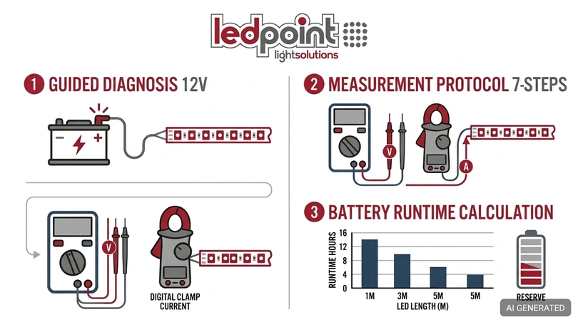
5. Professional measurement protocol with multimeter and DC clamp meter
Visual diagnosis is fine for getting oriented, but to close the case you need numbers. This measurement protocol requires a digital multimeter, a DC clamp meter, and about twenty minutes of work. It is the same procedure an auto electrician workshop uses to certify the behavior of an additional load installed on board, and it produces a complete picture of the system's behavior in all relevant conditions.
The seven fundamental measurements
| Measurement | Tool and position | Vehicle condition | Expected value on healthy system | Value indicating a problem |
| M1 - Battery rest voltage | Voltmeter at terminals | Key off for at least 2 hours | 12.6 - 12.8V | Below 12.4V repeatedly |
| M2 - Charging voltage | Voltmeter at terminals | Engine running, 2000 RPM | 13.8 - 14.8V | Above 15.0V or below 13.5V |
| M3 - Voltage at strip start | Voltmeter on input pads | Strip on, engine off | within 0.3V of battery voltage | Loss greater than 0.5V |
| M4 - Voltage at strip end | Voltmeter on last pads | Strip on, engine off | Contained difference compared to M3 | Difference greater than 10% of M3 |
| M5 - Current absorbed with engine off | DC clamp meter on positive | Strip on | Consistent with W/m × meters ÷ 12.6 | Deviation over 15% from calculation |
| M6 - Current absorbed with engine on | DC clamp meter on positive | Strip on, 2000 RPM | Practically equal to M5 | Increase of 30–60% compared to M5 |
| M7 - Total vehicle rest current | Clamp or multimeter in series | Everything off, ECUs in sleep | 20 - 50 mA (modern vehicle) | Over 80 mA with LED system connected |
The interpretation that makes the difference
The comparison between M5 and M6 is the most revealing measurement of all, and it is the one that no one performs. If the current absorbed by the strip increases significantly when you start the engine, you have definitive proof that your automotive LED system has no regulation and is working in overcurrent for the entire time the vehicle is running. On a constant current control strip, M5 and M6 are substantially identical: this is exactly the behavior you want to achieve.
Measurement M7, on the other hand, is the one that closes the "dead battery" case. A modern vehicle in sleep mode absorbs a few tens of milliamps to keep memories, alarm, and ECUs on standby. If after installing the automotive LED lights the rest current rises by 30, 50, or 80 mA, that current in a week of parking consumes from 5 to 13 Ah: enough to compromise the starting of a battery that is no longer new. The cause is almost always a controller or dimmer left on standby on a permanent positive.
The residual autonomy test
To quantify the real risk, there is a simple calculation. The usable capacity of a starter battery without compromising its life and starting ability is, prudently, 25-30% of the nominal capacity. On a 60 Ah battery, this means 15–18 Ah actually spendable.
| Meters of 8.6 W/m strip on | Total power | Current at 12.6V | Autonomy on 18 Ah reserve (60 Ah battery) | Autonomy on 30 Ah reserve (100 Ah leisure battery) |
| 1 m | 8.6 W | 0.68 A | about 26 hours | about 44 hours |
| 2 m | 17.2 W | 1.37 A | about 13 hours | about 22 hours |
| 3 m | 25.8 W | 2.05 A | about 8.8 hours | about 14.6 hours |
| 5 m | 43.0 W | 3.41 A | about 5.3 hours | about 8.8 hours |
| 7.5 m | 64.5 W | 5.12 A | about 3.5 hours | about 5.9 hours |
| 10 m | 86.0 W | 6.83 A | about 2.6 hours | about 4.4 hours |
This table is the most important design tool in the entire article: before installing a single meter of strip, you must know how many hours you can keep it on with the engine off. And it is also the reason why, in serious conversions, lighting is never connected to the starter battery but to a dedicated auxiliary battery.
6. Parasitic drain: when automotive LEDs drain the battery at night
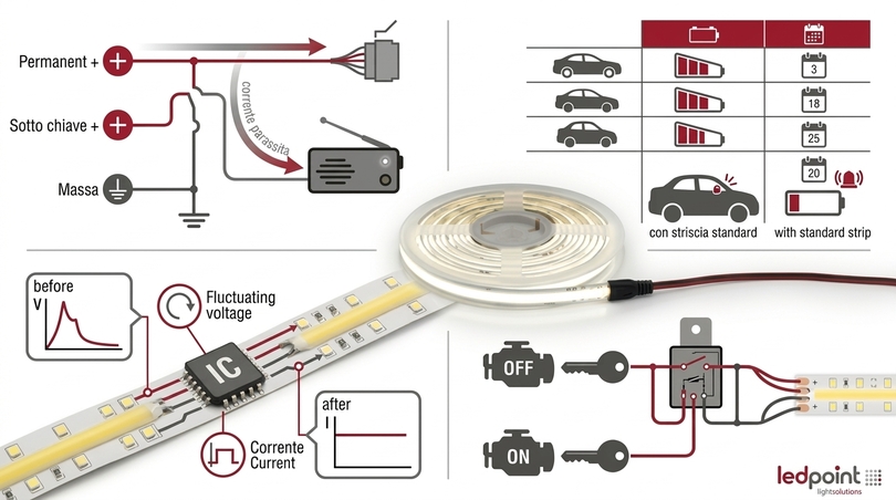
There is a category of faults that has nothing to do with the quality of the strip and everything to do with the point where power is drawn. Parasitic drain is the current that the system continues to draw when everything should be off, and it is the silent culprit in almost a fifth of the cases that occur with a dead battery after installing LED strips.
The sources are three, and they often coexist. The first is the direct connection to the permanent positive without any disconnecting device: just a switch left on by distraction and in one night several amp-hours are gone. The second is the standby of controllers and receivers: an RF receiver or a dimmer with remote control must stay in listening mode, and to stay in listening mode it typically consumes between 10 and 60 mA, always, twenty-four hours a day. The third, more insidious, is the leakage current through damaged insulation or oxidized connections, which in a humid environment can reach surprising values.
The calculation of the real impact
| Parasitic drain | Consumption in 24 hours | Consumption in 7 days | Consumption in 30 days | Outcome on 60 Ah battery |
| 10 mA | 0.24 Ah | 1.7 Ah | 7.2 Ah | Tolerable |
| 30 mA | 0.72 Ah | 5.0 Ah | 21.6 Ah | Critical after 3 weeks |
| 60 mA | 1.44 Ah | 10.1 Ah | 43.2 Ah | Starting compromised in 10-14 days |
| 150 mA | 3.6 Ah | 25.2 Ah | 108 Ah | Battery dead in less than a week |
| 500 mA | 12 Ah | 84 Ah | over capacity | Battery dead in 36-48 hours |
The operational rule is clear: no decorative or service lighting load should remain connected to the permanent positive without an automatic disconnecting device. The correct way is to power the automotive LED lighting system from an ignition-switched line, or to interpose a relay commanded by the ignition switch that opens the power circuit when the ignition is off. We will see both diagrams in detail later.
7. The technical solution: 12V constant current COB strip
We arrive at the heart of the guide. All the problems analyzed so far (voltage drop, overcurrent with engine running, unevenness, color shift, premature degradation) are solved simultaneously by adopting an LED strip that integrates a current regulation system on board. It is not an accessory to add: it is a different architecture of the product.
In a constant current strip, the passive resistor is replaced by a regulator integrated circuit that continuously compares the current flowing through the LEDs with an internal reference and keeps it constant regardless of the input voltage, within a declared operating range. The practical result is that the strip illuminates exactly the same way at 11.5V, 12.6V, and 14.4V, and that the absorbed power remains stable instead of growing with the onboard voltage. Translated into workshop language: no more overconsumption while driving, no more thermal stress, no more battery draining because the system consumes double what is declared.
Why COB technology is the right choice for automotive
The acronym COB stands for Chip On Board: the LED chips are mounted directly on the substrate and covered with a layer of phosphors, generating a continuous line of light instead of a sequence of bright dots. In the context of on-vehicle lighting, this characteristic is not aesthetic, it is functional.
| COB Characteristic | Advantage in automotive environment | Typical application |
| Continuous line of light without dotting | No "pearl necklace" effect reflected on glossy surfaces and glass | Cabin ambient light, under-dash, pillars |
| Wide emission angle (about 180°) | Uniform diffuse lighting without shadow zones | Cargo area, trunk, camper living cell |
| Extremely high chip density (384 led/m) | Better thermal distribution per chip for the same flux | Installations with long daily operating hours |
| Extended emitting surface | Less direct glare and greater visual comfort | Mobile workstations, workshops on wheels |
| Narrow 5 mm PCB | Housing in minimal profiles and reduced gaps | Grooves, recesses, moldings, camper furniture |
| High flexibility | Follows curves and fillets typical of car interiors | Shaped dashes, door panels, curved grooves |
The complete range is available in the category COB LED strips and in the technical section COB on Ledpoint.it, where each model reports the cutting pitch, width, height, and photometric characteristics.
The decisive role of CRI Ra>93
The Color Rendering Index measures the fidelity with which a source reproduces colors compared to a reference. In decorative lighting, an Ra of 80 may suffice; in functional lighting on board a vehicle, an Ra greater than 90 concretely changes the result of the work.
| Context of use | Minimum recommended CRI | Why |
| Mobile workshop, repairs, wiring diagnosis | Ra ≥ 90 | Reliable distinction of conductor colors and shades of rust and oxide |
| Camper and van cell, living area | Ra ≥ 90 | Prolonged visual comfort, natural rendering of skin, fabrics, and wood |
| Food truck and street vending | Ra ≥ 90 with high R9 | Realistic rendering of food, especially in red tones |
| Cargo area and logistics | Ra ≥ 80 | Reading labels and color codes |
| Decorative ambient lighting | Ra ≥ 80 | Primarily aesthetic function |
| Video shooting, content, mobile showcases | Ra ≥ 93 | Correct white balance and absence of color casts in post-production |
The Ra>93 value of the 10-meter COB strip from Ledpoint places the product in the professional tier, the one where light is not just used to show that there is light, but to correctly show what is being illuminated.
The 4000K color temperature: the rational choice for the vehicle
The choice of color temperature is not a matter of taste when it comes to operational environments. 4000K represents the optimal technical compromise between comfort and visual performance on board a vehicle, and it is no coincidence that it is the dominant tone in professional interior technical lighting.
| Color temperature | Perception | Strengths on board vehicle | Limitations |
| 2700 – 3000K (warm white) | Welcoming, domestic | Evening relaxation in camper cell | Low contrast in precision work, drowsiness |
| 3500K (warm natural white) | Neutral tending to warm | Living and kitchen areas | Less effective on dark surfaces |
| 4000K (natural white) | Neutral, soft daylight | Maximum readability without fatigue, excellent contrast, natural rendering | No significant limitations in the vehicle environment |
| 5000 – 5700K (cool white) | Clinical, technical | Inspection, quality control | Visual fatigue during long stays, "hospital" effect |
| 6000 – 6500K (daylight white) | Very cold, bluish | Maximum perceived contrast | Glare, poor comfort, disruption of night adaptation |
For applications requiring different tones, Ledpoint offers alternatives always with current control, such as the 5m cool white 6000-6500K 2835 30led/m 12V constant current control LED strip, useful where maximum contrast and contained consumption are needed.
8. Complete technical data sheet of the Ledpoint product and data reading
A technical data sheet is not meant to fill a product page: it is meant to size the system. Here you will find all the data of the 10-meter COB strip from Ledpoint translated into practical installation consequences, because every number corresponds to a design decision you will have to make.
| Parameter | Value | What it entails during installation |
| Technology | COB (Chip On Board) | Continuous line without dots, ideal for grooves and close diffusers |
| Coil length | 10 meters | Coverage of long sections without intermediate joints |
| Color temperature | 4000K natural white | Optimal comfort and rendering for functional and living use |
| Color rendering | CRI Ra > 93 | Professional tier, suitable for work, video, and food |
| LED density | 384 led/m | Extremely high uniformity even with diffuser a few millimeters away |
| Supply voltage | 12V DC | Direct compatibility with the vehicle's onboard network |
| Power | 8.6 W/m - 86 W total | Base for calculating current, cables, fuses, and autonomy |
| PCB width | 5 mm | Can be housed in very narrow profiles and gaps |
| Regulation system | Current control | Constant flux as onboard voltage varies: the key point |
| Support | Flexible with double-sided tape on the back | Quick installation even on curved surfaces, after degreasing |
How to read the "8.6 W/m" data in the automotive context
The power per meter value is the parameter from which all sizing descends. On a traditional strip, the nameplate data is valid only at exactly 12.0V and becomes progressively false as the voltage rises; on a constant current strip, the nameplate data remains valid over the entire operating range. This is a huge difference when sizing a fuse or calculating autonomy.
| Onboard voltage | Real power - traditional strip (nameplate value 8.6 W/m) | Real power - constant current strip | Deviation |
| 11.5V | about 5.5 W/m | about 8.6 W/m | The traditional one loses 36% of light |
| 12.0V | 8.6 W/m | 8.6 W/m | Coincidence only at this point |
| 12.6V | about 10.1 W/m | about 8.6 W/m | +17% unforeseen consumption |
| 13.8V | about 12.9 W/m | about 8.6 W/m | +50% unforeseen consumption |
| 14.4V | about 14.3 W/m | about 8.6 W/m | +67% unforeseen consumption |
Over ten meters, at 14.4V, the difference between the two architectures exceeds 55 watts: almost five extra amps drawn from the onboard network for no appreciable lighting benefit. Here, in one line, is why current control is not a technical whim but a design necessity in automotive lighting.
The advantage of the 5 mm PCB
The width of the printed circuit board seems like a secondary detail, but in vehicle interiors it is often the parameter that decides whether an installation is possible or not. With only 5 millimeters in width, this strip enters where an 8 or 10 mm tape cannot: under moldings, in the joints of door panels, in the grooves of camper wall units, in minimal profiles, in the cracks between panel and structure. The choice of the housing profile must still be made with criteria, and the range is available in the section aluminum profiles for LED strips and in the catalog profiles.
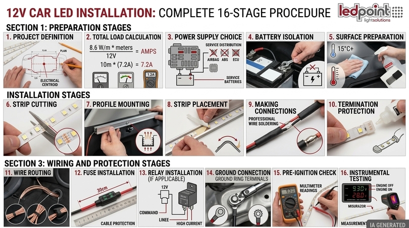
9. Step-by-step installation: the complete procedure in 16 phases
This is the operational section that turns theory into a working system. The following procedure is designed for a professional installation of automotive LEDs on a 12V vehicle, and is applicable to cars, vans, camper vans, commercial vehicles, and special conversions. Each phase contains the "what to do" and the "why", because it is the why that avoids mistakes.
Preparatory phase (phases 1-5)
Phase 1 - Definition of the lighting design: before touching a cable, measure the sections to be illuminated and define how many meters of strip are actually needed. Draw the path, identify the bending points, cable routing, and the position of the power supply point. The power supply point should always be positioned as close as possible to the electrical center of gravity of the system, not at the first convenient socket you find.
Phase 2 - Calculation of the total load: multiply the meters by 8.6 W/m and divide by 12 to get the nominal current. Ten complete meters absorb about 7.2 A. This number determines the cable gauge, fuse size, need for a relay or not, and impact on battery autonomy.
Phase 3 - Choice of power source: decide whether to power from an ignition-switched line, a commanded relay, an auxiliary battery, or a dedicated panel. Never draw current from safety circuits, airbag lines, ABS lines, or engine ECU wiring. The correct draw occurs on a sized service line or directly from a protected distribution bar.
Phase 4 - Battery disconnection: disconnect the negative battery terminal before starting any work on the system. On vehicles with sensitive electronic systems, check the manufacturer's procedure in advance and the need for radio codes or window resets.
Phase 5 - Surface preparation: the installation surfaces must be cleaned, degreased with isopropyl alcohol, and brought to room temperature (ideally above 15°C). 90% of adhesive tape peeling depends on an un-degreased surface or installation performed at low temperature. On low surface energy plastics, the use of a specific primer is mandatory, not recommended.
Installation phase (phases 6-10)
Phase 6 - Cutting the strip: cutting must be performed exclusively on the marked lines, with straight-blade scissors, perpendicular to the tape. Cutting outside the provided points compromises the segment and can disable the entire downstream section. Always check the cutting pitch indicated in the product data sheet before intervening.
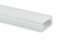
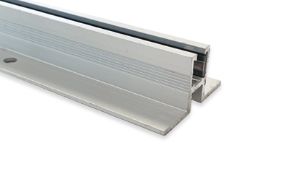
Phase 7 - Profile mounting: fix the aluminum profile before applying the strip. The profile performs three functions simultaneously: thermal dissipation, mechanical protection from vibrations, and support for the diffuser. In a vehicle, the profile is not an aesthetic accessory but a structural component of the system.
Phase 8 - Strip installation: remove the protective film of the double-sided tape progressively, not all at once, and press evenly without pulling the tape. A strip installed under tension will always peel off, sooner or later, because the PCB tends to return to its resting length. Respect the minimum bending radius and never bend the tape at the chips.
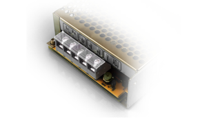
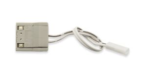
Phase 9 - Making connections: for automotive use, soldering is preferable to clip connectors, because continuous vibrations tend to degrade pressure contacts over time. If quick connectors are used, choose quality models and protect them mechanically. The range is available in PCB connectors for LED strips and connectors for LED strips. Every joint must be insulated with heat shrink tubing, never with electrical tape.
Phase 10 - Protection of terminations: cut sections must be sealed with end caps or resin, especially if installed in areas subject to humidity such as tailgates, under the cabin chassis, or storage compartments. Completion accessories are in the section accessories for LED strips.
Wiring and protection phase (phases 11-16)
Phase 11 - Cable laying. Use tinned copper cable with insulation suitable for the compartment temperature, sized according to the table in chapter 11. The cable must never be routed in contact with sharp edges, hot parts, or moving components, and every sheet metal crossing requires a rubber grommet.
Phase 12 - Fuse installation. The fuse must be installed on the positive conductor, as close as possible to the draw point, ideally within 30 centimeters. The fuse does not protect the strip: it protects the cable from fire in case of a short circuit. This distinction is fundamental and explains why the size is calculated based on the conductor's capacity, not the load's consumption.
Phase 13 - Relay installation (if provided). For loads over 5 A, do not let the current pass through a dashboard switch or an existing service line: use a 12V relay with adequate contacts, commanded by the ignition switch and powered from a protected line.
Phase 14 - Ground connection. The ground must be brought to a dedicated bodywork point, cleaned of paint, with a ring terminal, toothed lock washer, and screw tightened to torque. A poor ground generates exactly the same symptoms as a defective strip, and is one of the most underestimated causes of flickering and brightness drops.
Phase 15 - Pre-power-on check. Recheck the polarity with the multimeter before reconnecting the battery. Polarity reversal on an LED strip is one of the most expensive and frequent mistakes.
Phase 16 - Instrumental testing. Perform measurements M3, M4, M5, and M6 described in chapter 5, note the values, verify the absence of deviations between engine off and on, and check the tape temperature after thirty minutes of continuous operation. An automotive LED system is not finished when it turns on: it is finished when it has been measured.
10. The 5 wiring diagrams for the automotive LED system
There are five valid connection architectures for installing LED strips on a 12V vehicle, each with a precise field of application. Choosing the wrong diagram is the number one cause of battery problems, regardless of the quality of the installed strip. This table summarizes everything you need to decide.
| Diagram | Architecture | Recommended load | Risk of battery drain | Ideal application | Complexity |
| A - Direct ignition-switched | Draw on +15 line with dedicated fuse | up to 3-4 A | Null: turns off with ignition | Cabin ambient light, short sections | Low |
| B - Relay commanded by ignition | Power from protected battery, command from +15 | up to 15-20 A | Null in normal operation | Long sections, cargo areas, conversions | Medium |
| C - Manual switch with indicator | Protected line with visible disconnect | up to 8 A | Medium: depends on operator | Service lights to be used with engine off | Low |
| D - Auxiliary battery with charge separator | Independent secondary system | over 20 A | Null on the starter battery | Camper vans, vans, mobile workshops, food trucks | High |
| E - Stabilized DC-DC converter | Regulated 12V output from variable input | according to converter | Null if combined with A, B, or D | Strips lacking current control | Medium-high |
The recommended diagram for the 10-meter COB strip
With 86 W total and about 7.2 A absorption, the 10-meter COB strip falls fully within the range where Diagram B (relay commanded by ignition switch) represents the technically correct solution for use on a vehicle, and Diagram D for conversions with a leisure system. Here is the logical sequence of the connection in Diagram B:
| Point | Connection | Component | Technical note |
| 1 | Battery positive → fuse holder | 10 A Fuse | Within 30 cm of terminal, 2.5 mm² cable |
| 2 | Fuse holder → relay pin 30 | 12V 20/30 A Relay | Normally open power contact |
| 3 | Ignition-switched line → relay pin 86 | 0.75 mm² cable + 2 A fuse | Only coil excitation current |
| 4 | Relay pin 85 → bodywork ground | Ring terminal | Clean and dedicated ground point |
| 5 | Relay pin 87 → command switch | Dashboard switch | Allows turning off even with ignition on |
| 6 | Switch → strip positive input | 2.5 mm² cable | Respect polarity marked on PCB |
| 7 | Strip negative → bodywork ground | 2.5 mm² cable | Same ground point as the lighting system |
The advantage of this architecture is twofold: no parasitic drain with ignition off and no power current passing through original wiring not sized for the added load.
When dual-feed is still needed
Dual-feed (powering the strip from both ends) remains a valid technique, but with a constant current strip its purpose changes radically. It is no longer needed to recover luminous uniformity, but to reduce current density on the copper traces and therefore heating in the first meters. On installations that work many hours a day in a hot environment, distributing power to both ends is still a good engineering practice that extends the life of the product.
The role of power supplies in non-vehicle installations
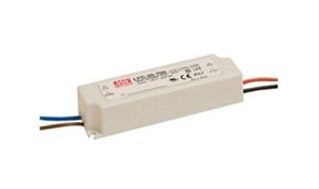
The same strip is also used in fixed contexts (workshop benches, displays, showcases, furnishings) where power comes from the mains. In that case, power supplies sized with a margin of at least 20–30% on the nominal power are needed. Solutions are in the categories 12V power supplies for LED strips, constant current power supplies, and power supply with integrated dimmer. For 86 W of load, a power supply of at least 110–120 W is needed, never a 90 W one which would not be sufficient.
11. Conversion tables: watts, amps, cable gauges, fuses, autonomy
This chapter is the real working tool of the article. These are the tables an installer keeps at hand during assembly, built specifically for the 8.6 W/m 12V strip and generalizable to any automotive LED light system.
Meters → power → current conversion
| Meters installed | Total power (W) | Current at 12.0V (A) | Current at 12.6V (A) | Current at 14.4V (A) | Recommended fuse |
| 0.5 | 4.3 | 0.36 | 0.34 | 0.30 | 2 A |
| 1 | 8.6 | 0.72 | 0.68 | 0.60 | 2 A |
| 2 | 17.2 | 1.43 | 1.37 | 1.19 | 3 A |
| 3 | 25.8 | 2.15 | 2.05 | 1.79 | 5 A |
| 4 | 34.4 | 2.87 | 2.73 | 2.39 | 5 A |
| 5 | 43.0 | 3.58 | 3.41 | 2.99 | 7.5 A |
| 6 | 51.6 | 4.30 | 4.10 | 3.58 | 7.5 A |
| 7.5 | 64.5 | 5.38 | 5.12 | 4.48 | 10 A |
| 8 | 68.8 | 5.73 | 5.46 | 4.78 | 10 A |
| 10 | 86.0 | 7.17 | 6.83 | 5.97 | 10 A |
| 15 (2 partial coils) | 129.0 | 10.75 | 10.24 | 8.96 | 15 A |
| 20 (2 coils) | 172.0 | 14.33 | 13.65 | 11.94 | 20 A |
Note: on a constant current strip, power remains constant and the absorbed current decreases slightly as voltage increases, for the same power delivered. It is the opposite behavior of traditional strips, and it is exactly what protects the battery.
Minimum cable gauge as a function of current and distance
The following table indicates the minimum cross-section in mm² to keep the voltage drop within 3% on an out-and-return path, which is the criterion adopted in good vehicle installation practice.
| Current | 1 m | 2 m | 3 m | 5 m | 7 m | 10 m |
| 1 A | 0.50 | 0.50 | 0.50 | 0.50 | 0.75 | 1.00 |
| 2 A | 0.50 | 0.50 | 0.75 | 1.00 | 1.50 | 2.00 |
| 3 A | 0.50 | 0.75 | 1.00 | 1.50 | 2.50 | 2.50 |
| 5 A | 0.75 | 1.50 | 1.50 | 2.50 | 4.00 | 4.00 |
| 7.5 A | 1.00 | 1.50 | 2.50 | 4.00 | 4.00 | 6.00 |
| 10 A | 1.50 | 2.50 | 2.50 | 4.00 | 6.00 | 6.00 |
| 15 A | 2.50 | 2.50 | 4.00 | 6.00 | 6.00 | 10.00 |
| 20 A | 2.50 | 4.00 | 4.00 | 6.00 | 10.00 | 10.00 |
Cable undersizing is the second most frequent mistake after connecting to a permanent positive, and it produces exactly the same symptoms as a defective strip: reduced brightness, heating, unstable behavior. In a vehicle, where distances between the battery and the point of use can exceed five meters, the difference between 1.5 mm² and 2.5 mm² is not a detail.
Quick conversion for power supply sizing
| Quantity to calculate | Formula | Example with 10 m of 8.6 W/m strip |
| Total power | W/m × meters | 8.6 × 10 = 86 W |
| Nominal current | Power ÷ voltage | 86 ÷ 12 = 7.17 A |
| Fuse size | Current × 1.25, rounded up | 7.17 × 1.25 = 8.96 → 10 A |
| Power supply power (fixed use) | Power × 1.25 minimum | 86 × 1.25 = 107.5 → 120 W |
| Daily energy consumption | Current × hours of operation | 7.17 × 3 h = 21.5 Ah per day |
| Autonomy on battery reserve | Reserve Ah ÷ current | 18 ÷ 7.17 = 2.5 hours |
| Voltage drop on cable | 2 × L × I × 0.0175 ÷ S | 2 × 3 × 7.17 × 0.0175 ÷ 2.5 = 0.30V |
12. Profiles, thermal dissipation, vibrations, and IP rating
An LED does not fail due to mechanical wear: it degrades due to heat. The junction temperature is the single factor that determines the useful life of any automotive LED system, and in a vehicle (where the cabin in summer easily exceeds 50°C and closed compartments go beyond) thermal management is not optional.
The mechanism is simple: every extra degree on the junction accelerates the depreciation of the luminous flux and the shifting of the phosphors. A strip laid in contact with a dissipating metal surface can work tens of degrees cooler than the same strip laid on plastic or glued inside a closed groove without circulation. The aluminum profile is not meant to look good: it serves to turn the support into a heatsink.
Temperature-lifespan correlation table
| Installation condition | Estimated overtemperature on tape | Impact on useful life | Recommendation |
| Ventilated aluminum profile | +10 / +15°C above ambient | Optimal reference | Recommended solution |
| Recessed aluminum profile | +15 / +25°C | Contained reduction | Acceptable with power margin |
| Direct lay on sheet metal | +15 / +25°C | Contained reduction | Acceptable if surface is wide |
| Direct lay on plastic | +30 / +45°C | Significant reduction | To be avoided over 5 W/m |
| Closed groove without circulation | +40 / +60°C | Marked reduction | Requires mandatory dissipating profile |
| Strip rolled up in coil while on | over +70°C | Permanent damage | Never power a rolled-up strip |
The last row deserves a special mention because it is a mistake you only make once: powering the coil to "do a test" before unrolling it means concentrating 86 watts in a few cubic centimeters of space. The damage is immediate and irreversible.
Vibrations: the specific enemy of automotive
Compared to a domestic installation, the vehicle introduces a stress that does not exist elsewhere: continuous vibration at variable frequencies and amplitudes. This stress acts on three specific weak points.
| Weak point | Effect of vibrations | Countermeasure |
| Conductor soldering on pads | Fatigue cracks, intermittent contacts | Strain relief with tubing and fixing cable 5 cm from pad |
| Clip connectors | Progressive loosening, oxidation | Prefer soldering, or quality clips mechanically locked |
| Support adhesive | Progressive peeling from ends | Housing profile and mechanical fixing at extremes |
| Loose cables in trunking | Insulation abrasion against edges | Cable ties every 20–30 cm and rubber grommets |
| Terminal blocks and fuse holders | Loosening of screws | Spring washers and periodic torque check |
IP rating: choosing based on the compartment
The IP code defines protection against solid bodies and liquids. In the automotive environment, the choice must be made compartment by compartment, because conditions change radically from one point to another of the same vehicle.
| Installation zone | Minimum IP rating | Motivation |
| Cabin, dash, interior door panels | IP20 | Dry and protected environment |
| Camper cell, living area | IP20 | Controlled environment, except shower area |
| Van cargo area | IP20 / IP54 | Dust and occasional humidity from tailgate |
| Trunk, storage compartments, under-door interior | IP54 | Humidity and dirt infiltration |
| Camper shower and kitchen area | IP65 | Direct splashes |
| Undercarriage, exteriors, external storage | IP67 / IP68 | Pressurized water, washes, temporary immersion |
13. CAN bus, dashboard errors, and electromagnetic compatibility
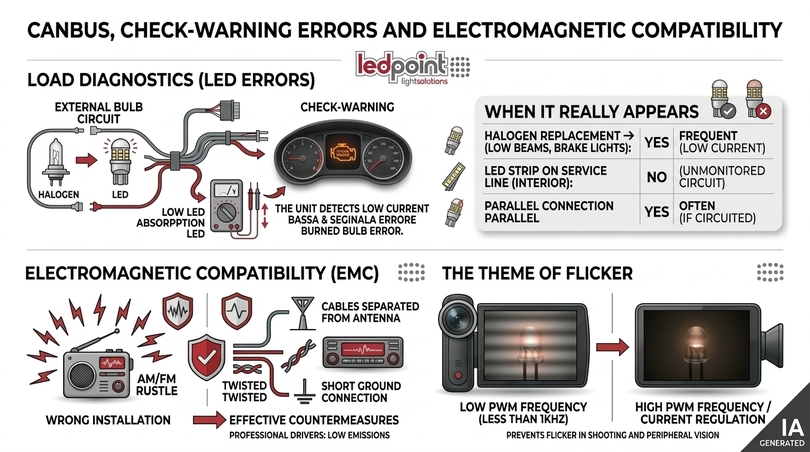
The chapter that generates the most confusion in the world of automotive LEDs is the one related to CAN bus. A fundamental misunderstanding must be clarified immediately: CAN bus is not a bulb control system, it is the communication protocol between the vehicle's ECUs. When talking about "CAN bus errors" with LEDs, we are actually talking about load diagnostics: some ECUs measure the current absorbed by a lighting circuit to verify that the bulb is intact, and when that current drops too low (as happens when replacing a halogen bulb with an LED) they interpret the data as a burnt bulb.
This phenomenon almost exclusively concerns automotive LED bulbs that replace halogen bulbs on diagnosed circuits: low beams, position lights, turn signals, brake lights, reverse lights. Interior LED strips installed on a dedicated service circuit do not generate CAN bus errors, because they do not replace anything and are not monitored by any ECU. This is exactly why the connection diagram with relay and dedicated line, described in chapter 10, is the safest solution also from a diagnostic point of view.
When the error actually appears
| Situation | Does it generate an error? | Why | Solution |
| LED strip on service line with relay | No | Circuit not monitored by diagnostics | No action necessary |
| LED strip connected in parallel to courtesy lights | Rarely | Some vehicles monitor the ceiling light circuit | Move to dedicated line |
| LED strip connected to position light circuit | Yes, often | Load diagnostic on exterior lights | Dedicated line with relay |
| Replacing halogen bulb with LED | Yes, frequently | Absorbed current much lower than expected | Bulbs with load resistor or CAN bus versions |
| Draw from cigarette lighter line | Rarely | Circuit generally not diagnosed | Check capacity of existing fuse |
Electromagnetic compatibility and radio interference
A poorly designed switching driver can emit conducted and radiated disturbances that manifest as hiss on the AM radio, degradation of reception, or interference on onboard wireless systems. Electromagnetic compatibility is one of the parameters that separates a professional component from a low-end product, and it is worth checking it before purchase, not after.
The installation countermeasures that drastically reduce the problem are three: keep the strip's power cables physically separated from antenna and audio wiring, twist positive and negative along the path to minimize the loop area, and make a short, low-impedance ground connection. A well-wired automotive LED system disturbs nothing; a poorly wired system can render the vehicle's radio unusable.
The issue of flicker
Flickering is a little-considered but relevant aspect, especially for those who spend many hours on board or create video content. Strips powered directly in DC with current regulation have an intrinsically very low flicker. The problem arises with intensity regulation: Pulse Width Modulation at frequencies below the kilohertz produces flicker perceptible in peripheral vision and evident beatings in video recordings. If the system must be dimmable, always choose devices with high PWM frequency, or adopt current regulation.
14. Regulations and approval: what you can actually install
This section deserves maximum attention because it is where the most incorrect information is concentrated. The fundamental distinction is between interior lighting and exterior lighting devices: they are two completely different regulatory regimes.
Exterior lighting and visual signaling devices of a vehicle are subject to approval according to international harmonized regulations and the provisions of the Highway Code. Every exterior device must bear the European approval mark, and its installation must respect the position, color, intensity, and function provided for. The technical regulations of reference are published by the United Nations Economic Commission for Europe. A generic LED strip is not an approved exterior lighting device and cannot be installed as such on a vehicle circulating on public roads.
Interior lighting of the cabin and compartments follows a different logic, based on the principle of non-interference with driving and other road users. The substantial criteria that any interior installation must respect are summarized in the following table.
| Criterion | Practical rule | Motivation |
| Visibility from outside | The source must not be visible or perceptible from outside the moving vehicle | Avoid confusion with approved signaling devices |
| Colors | Avoid red, blue, and flashing in any visible position | Reserved for emergency vehicles and specific functions |
| Driver glare | No direct source in the field of vision or reflected on the windshield | Driving safety |
| Distraction | No dynamic effects, flashing, or color change while driving | Distraction prevention |
| Electrical safety | Circuit protected by dedicated fuse, compliant wiring | Fire prevention |
| System modifications | No alteration of safety circuits or approved devices | Vehicle compliance |
The golden rule, simple and always valid: if the light is seen from outside while the vehicle is circulating, an approved device is needed; if it illuminates the interior and is not perceptible from outside, it is ambient lighting. For installations on fitted commercial vehicles, special means, converted camper vans, and professional conversions, prior verification at the Motor Vehicle Department or with a technical consultant remains the safest route, because modifications that affect the constructive characteristics of the vehicle require specific authorization paths.
The case of LED bulbs approved for headlights
The topic of approved automotive LED bulbs for low and high beam headlights, which is highly searched, deserves a note. Over the years, provisions have been introduced that allow, in specific cases and for determined vehicle-headlight-bulb combinations, the use of LED retrofit sources with certification. The essential condition is that the specific combination is covered by a certification that explicitly reports the vehicle model and the type of headlight, not that the bulb is generically "approved".
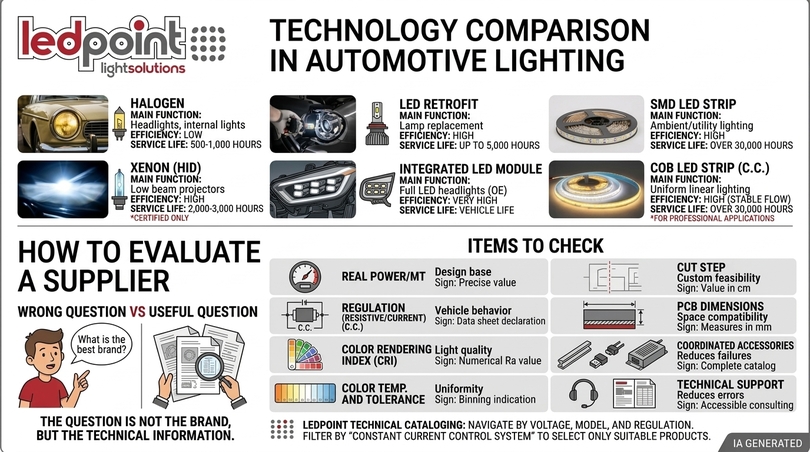
15. Comparison of technologies in automotive lighting
To navigate the market of automotive LEDs, a clear map of the available technologies and their field of application is needed. No technology is "the best" in absolute terms: each is the best for a specific task, and confusing their roles is at the origin of most wrong choices.
| Technology | Main function | Typical efficiency | Indicative lifespan | Field of application |
| Halogen | Headlights, indicators, traditional interior lights | low | 500 – 1,000 hours | Original equipment on older vehicles |
| Xenon (HID) | High-intensity low beam projectors | medium-high | 2,000 – 3,000 hours | Original high-end projectors |
| Retrofit LED bulb | Bulb replacement in existing projectors | high | up to 5,000 hours | Only with certification for the specific combination |
| Integrated LED module | Full LED headlights of original equipment | very high | life of the vehicle | Original design by the manufacturer |
| SMD LED strip | Ambient and service lighting | high | over 30,000 hours | Interiors, compartments, conversions |
| Constant current COB LED strip | High-quality uniform linear lighting | high with stable flux | over 30,000 hours | Interiors, camper vans, vans, mobile workshops, professional conversions |
How to evaluate a lighting component supplier
The question "what is the best brand of LED bulbs" recurs constantly, but it is poorly formulated. The useful question is not which brand is the best, but what technical information the supplier makes available before purchase. A professional supplier declares and documents; an amateur supplier shows only a photo and a price.
| Element to verify | Why it is decisive | Signal of reliability |
| Declared real power per meter | Base of any electrical sizing | Precise value, not "about" |
| Type of regulation (resistive or current) | Determines behavior on board vehicle | Explicit declaration in data sheet |
| Color rendering index | Real quality of light | Numerical Ra value, not "high rendering" |
| Color temperature with tolerance | Uniformity between different coils | Indication of binning |
| Cutting pitch | Feasibility of custom project | Value in cm or number of chips |
| PCB dimensions | Compatibility with profiles and spaces | Width and height in mm |
| Availability of coordinated accessories | Reduces system failure points | Profiles, connectors, power supplies in catalog |
| Pre- and post-sales technical support | Reduces design time and errors | Accessible technical consultancy |
The technical cataloging of the Ledpoint catalog responds to this logic: strips are classified by voltage, by LED model, by density, and by regulation technology, as can be seen by browsing the categories 12V LED strips and LED strips. Being able to filter by "constant current control system" means being able to select only the products suitable for vehicle use upstream, which is exactly the selection criterion that this guide recommends.
16. The 12 mistakes that destroy an automotive LED lighting system
After seeing what to do, it is worth explicitly listing what not to do. Each of these twelve mistakes is documented by thousands of real cases, and each produces a specific and predictable fault.
| # | Mistake | Consequence | Correct behavior |
| 1 | Connecting to permanent positive without disconnecting | Dead battery after a few days | Ignition-switched power or commanded relay |
| 2 | Using a 12V resistor strip on a vehicle | Overcurrent of 50–67% with engine running | Constant current control strip |
| 3 | Undersizing the cable gauge | Voltage drop, heating, dim light | Calculation with the table in chapter 11 |
| 4 | Omitting the fuse or placing it far from the draw | Fire risk in case of short circuit | Fuse within 30 cm of the draw point |
| 5 | Drawing current from safety circuits | Severe malfunctions, ECU errors | Dedicated and protected service line |
| 6 | Laying the strip without degreasing the surface | Peeling after a few weeks | Cleaning with isopropyl alcohol and primer |
| 7 | Installing without a dissipating profile | Overtemperature and accelerated degradation | Aluminum profile always, over 5 W/m |
| 8 | Powering the strip while still rolled up | Immediate and irreversible thermal damage | Completely unroll before powering on |
| 9 | Cutting outside marked points | Non-functioning segment or dead section | Cutting exclusively on marked lines |
| 10 | Insulating joints with electrical tape | Failure with heat and vibrations, short circuits | Heat shrink tubing on every joint |
| 11 | Using a painted or shared ground point | Flickering, brightness drops, disturbances | Dedicated ground on bare metal with ring terminal |
| 12 | Not measuring anything after installation | Latent problems that emerge months later | Instrumental testing according to chapter 5 |
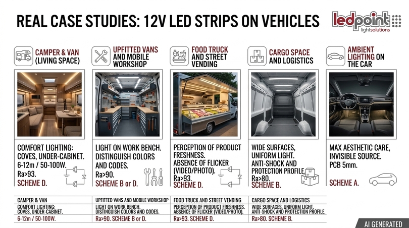
17. Real case studies: camper vans, vans, workshops, food trucks, custom builds
Theory finds its verification in application cases. These five scenarios cover almost all professional installations of 12V LED strips on vehicles, and show how the same principles are declined differently depending on the context.
Camper vans and vans: lighting the living cell
It is the most demanding application in absolute terms, because it combines long sections, many daily operating hours, power from an auxiliary battery, and high visual comfort requirements. In a camper van cell, typically between 6 and 12 total meters of strip are installed, distributed on perimeter grooves, under wall units, kitchen area, sleeping area, and storage compartments. The overall load easily exceeds 60-100 W, and the choice of 4000K color temperature with CRI Ra>93 guarantees that quality of light that makes the environment livable for weeks instead of simply illuminated.
The correct architecture is Diagram D: separate auxiliary battery, charge separator, protected distribution panel, separate lines per zone with independent switches. The advantage of the constant current strip is maximum here, because the auxiliary battery works between 11.8V at the end of discharge and 14.4V during charging, and without regulation the brightness in the cell would visibly change during the day. A 10-meter coil covers the entire perimeter without joints, eliminating dozens of potential failure points.
Fitted van and mobile workshop
Here the priority is the quality of light on the workbench and mechanical reliability. High color rendering becomes an operational requirement: distinguishing a brown cable from a dark red one, evaluating corrosion, reading a stamped code requires an Ra greater than 90. The strip should be installed in a profile with an opal diffuser to eliminate direct glare, powered with Diagram B or D and sectioned by zones.
Food truck and street vending
In the food sector, color rendering has a direct commercial impact: the perception of the freshness of the displayed product depends in a measurable way on the quality of the light that illuminates it, in particular on the rendering of reds. A CRI Ra>93 with good rendering of saturated red is the correct standard. Furthermore, the absence of flicker is essential because video content and product photos are taken right under that light.
Cargo area and logistics
The need is to cover wide surfaces with uniform light, in a hostile environment made of impacts, dust, and continuous handling. The protection profile is not optional but structural: the strip must be recessed and protected behind a resistant diffuser. Automatic turning on when the tailgate opens, with a turn-off timer, is the solution that eliminates at the root every risk of forgetting and therefore of a dead battery.
Ambient lighting on a car
In the cabin of a passenger car, the challenge is the opposite: short sections, contained power, maximum aesthetic care, and absolute invisibility of the source. The 5 mm PCB is decisive because it allows insertion into grooves, under-dash panels, moldings, and joints where no other format would fit. The correct connection is Diagram A, on an ignition-switched line, with a dedicated small-size fuse.
| Application | Typical meters | Power | Recommended diagram | Required CRI | Profile |
| Camper / van living | 6 – 12 m | 50 – 100 W | D (auxiliary battery) | Ra ≥ 93 | Recessed with opal diffuser |
| Mobile workshop | 4 – 8 m | 35 – 70 W | B or D | Ra ≥ 93 | Robust protruding |
| Food truck | 5 – 10 m | 45 – 86 W | D | Ra ≥ 93 | Sanitizable recessed |
| Cargo area | 3 – 8 m | 25 – 70 W | B with tailgate contact | Ra ≥ 80 | Anti-impact protected |
| Car ambient light | 1 – 3 m | 8 – 26 W | A (ignition-switched) | Ra ≥ 80 | Minimal or none |
18. Maintenance, lifespan, warranty, and total cost of ownership
A well-designed automotive LED system requires very little maintenance, but very little does not mean none. An annual twenty-minute check prevents almost all the faults that manifest themselves years later.
| Intervention | Frequency | What to check | Time required |
| Visual check of the tape | Annual | Peeling, yellowing, dead chips | 5 minutes |
| Terminal block tightening check | Annual | Loosening from vibration | 5 minutes |
| Diffuser cleaning | Six-monthly | Dust accumulation that reduces flux | 3 minutes |
| Rest current measurement | Annual | Appearance of parasitic drains | 10 minutes |
| Ground point check | Biennial | Oxidation and contact resistance | 5 minutes |
| Grommet inspection | Biennial | Insulation abrasions | 10 minutes |
The calculation of the total cost of ownership
The comparison between an economical product and a professional product should not be made on the purchase price but on the cost over ten years, including the value of the installation time. It is the labor, not the material, the dominant cost item in any on-vehicle installation, and this completely changes the arithmetic of the choice.
| Item | Generic economical strip | Constant current COB strip |
| Initial material cost | Low | Higher |
| Expected lifespan in vehicle environment | 1 - 3 years | over 8 - 10 years |
| Number of re-installations in 10 years | 3 - 5 | 0 - 1 |
| Cumulative labor hours | high | reduced to initial assembly |
| Real energy consumption while driving | up to +67% of nominal | equal to nominal |
| Risk of fault to the vehicle battery | concrete | negligible with correct diagram |
| Quality of light over time | evident depreciation and shift | stable |
| Total cost over 10 years | clearly higher | clearly lower |
19. Questions from professionals: electricians, designers, buyers, workshops
This section directly answers the questions that most frequently come from the different professional profiles dealing with lighting. The needs change radically depending on the role, but the underlying technical answer remains the same: current control, correct sizing, documented components.
For the electrician and installer
How do I choose the most efficient components for my clients? The criterion is not the lumen per watt declared in ideal conditions, but the flux actually maintained in real operating conditions. A strip that loses 30% of its light at the end of the run and consumes 50% more at 14.4V is not efficient, whatever the data sheet says. The selection parameter is the presence of current control.
Which products are the most durable over time? Those that work at a contained junction temperature. In order: constant current control, dissipating profile, high chip density that distributes the thermal load, power supply sized with a margin.
How do I reduce maintenance costs? By eliminating failure points. A continuous 10-meter coil instead of two 5-meter ones eliminates a joint; a solder joint instead of a clip connector eliminates a degradable contact; a profile instead of just double-sided tape eliminates the risk of peeling.
For the lighting designer
How do I integrate these solutions into a lighting design project? Starting from the continuity of the line of light. COB technology allows designing continuous cuts of light, without dotting, with extremely high uniformity even a few millimeters from the diffuser: this is what allows drawing clean architectural lines instead of sequences of dots.
How do I guarantee energy efficiency? By designing on the flux actually needed and not on the maximum available. An oversized strip then dimmed to 40% consumes more and performs worse than a correctly sized strip at 100%.
For the purchasing manager
How do I compare products from different suppliers? By building a matrix on six mandatory parameters: real power per meter, type of regulation, CRI with numerical value, color temperature with tolerance, LED density, PCB dimensions. If a supplier does not declare even just one of these six parameters, comparison is impossible and the product should be excluded a priori.
How do I get technical support for installation? By choosing suppliers who offer pre-sales consultancy on sizing and who have the entire chain of coordinated accessories in their catalog.
For the workshop owner
How do I improve the lighting of my garage or my service vehicle? With continuous linear light with high color rendering positioned in a way that eliminates self-shadows on the workbench. Two parallel lines at 4000K render much more than a single powerful central spotlight, because they eliminate shadows instead of moving them.
Which products are the easiest to install? Those that do not require accessory electronics. A constant current strip connects directly to the vehicle's 12V with a fuse and relay: no DC-DC converters, no stabilizers, no extra boxes to house and diagnose in case of failure.
20. FAQ - All the answers about automotive LEDs and the 12V battery
Below are the complete answers to the most frequent questions about automotive LEDs, 12V LED strips, battery problems, installation, and regulations. Click on each question to expand the answer.
Why do LED strips drain my car battery?There are three causes and they often coexist. The first is the connection to a permanent positive, which leaves the system powered even with the ignition off and generates a continuous parasitic drain. The second is the lack of current regulation: with the engine running, with the network at 14.4V, a resistor strip absorbs up to 67% more power than declared. The third is the oversizing of the system to compensate for voltage drop. The solution combines ignition-switched or relay power supply and the adoption of a constant current control strip. |
What exactly is voltage drop in an LED strip?It is the progressive loss of voltage along the copper traces of the strip, due to the resistance of the copper multiplied by the current flowing through it. Since the first section must carry the current of the entire strip, the available voltage decreases as you move away from the power supply point. On a traditional strip, this translates into decreasing brightness and a shift of the white towards warmer tones. |
What does "current control" mean in an LED strip?It means that each segment of the strip contains an integrated circuit that actively regulates the current flowing through the LEDs, keeping it constant as the supply voltage varies within the declared operating range. The result is uniform brightness and color over the entire length and stable absorbed power, regardless of the oscillations of the vehicle's onboard network. |
Why can a constant current strip be 10 meters long at 12V?Because the active regulation makes the voltage drop along the tape irrelevant: as long as the local voltage remains above the minimum operating threshold of the regulator, the current in the LEDs does not change. A traditional resistor strip, on the other hand, sees the current decrease proportionally to the voltage drop, and becomes unusable beyond 5 meters. |
How much does the 8.6 W/m COB strip actually consume?Eighty-six watts over the full ten meters, corresponding to about 7.2 A at 12V. The fundamental fact is that, thanks to current control, this value remains practically constant even with the engine running and the network at 14.4V, while a traditional strip of the same rating would reach over 140 W under the same conditions. |
How long can I keep the strips on with the engine off?It depends on the usable reserve of the battery and the meters turned on. On a 60 Ah starter battery, with a prudent reserve of 18 Ah, ten meters on last about 2.5 hours, five meters about 5.3 hours, and three meters about 8.8 hours. On a 100 Ah auxiliary battery, the times more than double. For prolonged use with the engine off, the correct solution is always a dedicated auxiliary battery. |
Do I need a DC-DC converter to install these strips on the car?No. This is precisely the advantage of the current control architecture: the regulation is already integrated into the strip, so no external converter or stabilizer is needed. The DC-DC converter remains necessary only for traditional resistor strips, which would otherwise constantly work out of spec. |
What is the best connection diagram for 10 meters of strip?The diagram with a relay commanded by the ignition switch: power drawn from the battery through a 10 A fuse placed within 30 cm of the terminal, relay power contact of at least 20 A, coil excited by the ignition-switched line with a 2 A fuse, command switch downstream of the relay, and dedicated ground on the bodywork. 2.5 mm² cables on the power line for paths up to about 3 meters. |
What fuse should I put?The rule is nominal current multiplied by 1.25, rounded to the next commercial size, verifying that the chosen cable has adequate capacity for that size. For ten meters of strip (7.2 A) the correct fuse is 10 A. The fuse protects the cable, not the strip: this is why the size is always verified against the conductor cross-section. |
Is dual-feed still needed with a constant current strip?Not for luminous uniformity, which is already guaranteed by the regulation. It can remain useful on highly stressed installations to reduce the current density on the traces in the first meters and therefore local heating. It is a good engineering practice, not a functional necessity. |
Why does the strip turn off when I start the engine?During starting, the network voltage drops for a few hundred milliseconds, with minimums that in cold diesels can drop below 9V. A strip without regulation, powered at that voltage, turns off or flickers visibly. With a current control architecture, the phenomenon is much attenuated or absent, because the regulator continues to work down to its minimum threshold. |
Do LED strips generate CAN bus errors?LED strips installed on a dedicated service line do not generate errors, because they do not replace any lamp monitored by load diagnostics. Errors typically appear when replacing halogen bulbs with LEDs on diagnosed circuits, because the ECU measures a current too low and interprets it as a burnt bulb. |
How do I eliminate a burnt light error with LED bulbs?There are two possible ways: use bulbs designed with circuits that simulate the absorption expected by the diagnostics, or — for additional lighting systems like strips — move the connection to a dedicated, unmonitored service line, with its own relay and fuse. The second is almost always the technically best solution. |
Can I mount LED strips on the outside of the car?Exterior lighting and visual signaling devices visible from the outside of a vehicle circulating on the road must be approved and installed according to the position, color, and function provided for by regulations. A generic LED strip is not an approved exterior lighting device and cannot be used as such. The correct use is in interior lighting, not perceptible from the outside while driving. |
Is interior ambient lighting allowed?Interior lighting is allowed when it is not visible from the outside while driving, does not dazzle or distract the driver, does not use colors reserved for signaling devices or emergency vehicles, does not produce dynamic effects while driving, and is made with wiring protected to the rule of art. For conversions on commercial vehicles or converted camper vans, prior verification at the Motor Vehicle Department is the most prudent route. |
Why is the end of my strip a different color?Because white LEDs powered below the nominal current shift their tone towards the warm. It is the visual manifestation of the voltage drop along the tape, and it is completely eliminated by adopting a constant current control strip, where the current in the chips remains unchanged from the beginning to the end of the section. |
Why 4000K and not 6000K?Because 4000K offers the best compromise between visual contrast and prolonged comfort. Tones above 5700K increase perceived contrast but tire during long stays, disturb night adaptation, and return an environment perceived as cold and clinical. In residential vehicles and mobile workstations, 4000K is the reference standard. |
What difference does a CRI Ra greater than 93 make?It makes the difference between seeing that there is light and correctly seeing what is illuminated. With Ra>93, the colors of electrical cables are distinguishable without errors, skin and fabrics appear natural, food maintains a realistic appearance, and video recordings do not require color cast correction in post-production. |
Do I need an aluminum profile even in a car?Yes, and in a car more than anywhere else. The profile performs three simultaneous functions: it dissipates heat by lowering the junction temperature and extending the life of the chips, it protects the tape from the continuous vibrations typical of the vehicle, and it supports the diffuser that eliminates direct glare. Over 5 W/m it becomes practically mandatory. |
Can I power the strip while it is still rolled up to do a test?Absolutely not. Powering a rolled-up coil concentrates all the power in a very small volume without any possibility of dissipation, producing immediate and irreversible thermal damage. The strip must always be completely unrolled before any power-on test. |
Where do I cut the strip?Exclusively on the cutting lines marked on the tape, with straight-blade scissors and a perpendicular cut. The cutting pitch is indicated in the product data sheet and corresponds to a precise number of chips. Cutting outside those points compromises the affected segment and can disable the entire downstream section. |
Is it better to solder or use clip connectors?In the automotive environment, soldering is decidedly preferable, because continuous vibrations tend to degrade pressure contacts over time. If you opt for quick connectors, quality models must be chosen, mechanically locked, and protected from strain. Every joint, soldered or clipped, must be insulated with heat shrink tubing. |
What cable gauge should I use?It depends on current and distance. For 7.2 A over a three-meter path, the correct cross-section is 2.5 mm²; over five meters it rises to 4 mm². The criterion is to keep the voltage drop within 3% on the out-and-return path. Cable undersizing produces exactly the same symptoms as a defective strip. |
How do I check if I have a parasitic drain?With a DC clamp meter on the positive battery cable, with the vehicle completely off and after waiting for all ECUs to enter sleep mode. A modern vehicle typically absorbs between 20 and 50 mA. Values above 80 mA after installing a lighting system indicate a connection problem. |
Is the strip dimmable?Yes, through compatible regulation devices. The technical advice is to choose dimmers with a high modulation frequency, to avoid flicker perceptible in peripheral vision and beatings in video recordings. It must also be remembered that an oversized strip then dimmed to 40% consumes more and performs worse than a correctly sized strip. |
How long does an LED strip installed on a vehicle last?The useful life depends almost entirely on the junction temperature and the stability of the current. A constant current control product, installed in a dissipating profile and powered correctly, easily exceeds 30,000 hours of operation with contained flux depreciation. The same product glued in a closed groove and powered in overcurrent can degrade visibly in a year. |
Can I connect two 10-meter coils in series?Never in series on the tape: the correct connection is in parallel, with power brought to each coil via dedicated cables of adequate cross-section starting from a common distribution point. Connecting twenty meters in cascade means making the current of both coils pass through the copper of the first, with unacceptable heating and drops. |
What is the difference between a COB strip and an SMD strip?In an SMD strip, the LEDs are discrete components spaced apart, and the result is a sequence of bright dots that requires distance or diffusers to be uniformed. In a COB strip, the chips are mounted directly on the substrate and covered with a layer of phosphors, generating a continuous line of light without dotting, with a wider emission angle and greater visual comfort at short distances. |
What brand of car LED bulbs is best to choose?The correct question does not concern the brand but the available technical documentation. For retrofit bulbs destined for headlights, only the certification referring to the specific vehicle-headlight-bulb combination counts. For interior lighting strips, declared real power, type of regulation, numerical CRI, color temperature with tolerance, LED density, and PCB dimensions count. |
Why does the light change intensity when I start the engine?Because the onboard network goes from about 12.6V with the engine off to 13.8–14.8V with the engine running, and a strip without regulation passively follows this variation by increasing current and flux. It is the most direct symptom of the lack of current control and is also the cause of the overconsumption that tires the battery. |
Can I install the system myself or do I need a professional?An installation on an ignition-switched line with contained load is within the reach of those with good manual skills and adequate tools. Interventions on higher power systems, direct draws from the battery, relay installation, creation of auxiliary systems, and conversions on commercial vehicles require specific electrotechnical skills and should be entrusted to a professional, both for safety and for vehicle compliance. |
21. Automotive LEDs and compatibility: a factor not to be underestimated
The 12V battery problem in cars with LED strips is not a battery problem. It is a problem of incompatibility between a component designed for a stabilized network and an electrical network, that of the vehicle, which is not stabilized. Once this is understood, everything else becomes linear: the voltage drop along the tape explains the luminous unevenness, the oscillation of the onboard voltage explains the overconsumption and premature degradation, and the connection to the permanent positive explains the dead battery in the morning.
The technical answer to all three phenomena is one and acts upstream: adopting an LED strip designed with an integrated current control system, correctly sizing cables and protections, and powering it through a circuit that opens when the vehicle is off. Three decisions, made just once in the design phase, that definitively eliminate a category of faults that otherwise recurs infinitely.
The COB LED strip 10m white 4000K CRI Ra>93 384led/m 12V 8.6W/m PCB 5mm constant current control responds point by point to this specification: ten continuous meters without joints, uniform flux from the beginning to the end of the section, stable absorbed power as the onboard voltage varies, professional-tier color rendering, optimal color temperature for operational environments, and a PCB of only 5 millimeters that enters where no other format enters. It is the component that turns an automotive LED installation from a compromise into a project.
The working method, in summary, is this: measure before buying, calculate before installing, test before closing the panels. An automotive LED system designed with these criteria is not touched again for ten years, and the vehicle's battery will not even notice it exists. For the sizing of specific projects, the selection of housing profiles, power supplies, and completion accessories, the complete technical catalog is available on Ledpoint.it.
This article was developed with the support of artificial intelligence and subsequently revised, corrected, and validated by the technical team of Ledpoint.it, which guarantees its reliability and compliance with official sources.